The challenges of large-part machining
Large workpieces expose every weakness in a fixture stack. Long overhang, heavy loading, and repeated crane or hoist handling make it much easier for chips, hose routing, and uneven support to interfere with positioning quality.
- More unsupported span: large weldments, housings, and structural parts magnify bending and twist if the receiver layout is too sparse.
- Harder air routing: existing tables or sub-plates often do not have through-table pneumatic passages, especially in retrofit projects.
- Higher setup risk: when a part takes time to load, any hose snag, access issue, or awkward unclamp step turns into lost spindle time.
When side-inlet routing beats bottom-inlet routing
Bottom inlet is ideal when you can design air passages into the table or sub-plate from the beginning. Side inlet becomes the more practical choice when you are retrofitting an existing machine, need fast deployment on a legacy fixture, or want maintenance access without dismantling the whole base.
| Situation | Why side inlet helps | What to control |
|---|---|---|
| Existing plate with no through-table air routing | Lets you add quick-change receivers without remachining the entire table | Protect hoses with guards and strain relief |
| Large fixture where the top surface is crowded | Moves plumbing to the side so pallets, stops, and work supports stay accessible | Plan hose exits away from crane hooks, forks, and chip wash |
| Maintenance-first retrofit project | Quick-disconnects stay reachable without lifting the full plate stack | Label lines and verify consistent unclamp timing across receivers |
Catalog-backed receiver classes for large parts
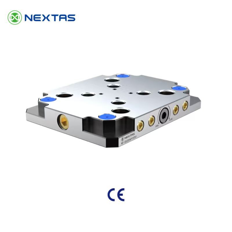
The current receiver family already shows how sizing changes with the application. In the general zero-point range, the NT-S200P120V1 is a 12 kN receiver with 100 kg lifting capacity, the NT-S200P160V1 moves to 18 kN and 250 kg, and the NT-S200P195V1 reaches 40 kN with 300 kg lifting capacity - all positioned as ≤ 0.003 mm repeatability modules.
| Receiver | Repeatability | Clamping force | Lifting load | Typical use |
|---|---|---|---|---|
| NT-S200P120V1 | ≤ 0.003 mm | 12 kN | 100 kg | Medium fixtures, modular sub-plates, lighter structural parts |
| NT-S200P160V1 | ≤ 0.003 mm | 18 kN | 250 kg | Larger plates, heavier carriers, roughing with more support demand |
| NT-S200P195V1 | ≤ 0.003 mm | 40 kN | 300 kg | Heavy plates, large-part stations, and cells prioritizing rigidity |
Across this family, the catalogue repeatedly highlights taper positioning, mechanical self-locking, self-cleaning locating surfaces, air-tightness testing, and inner-hole cleaning. Those functions matter even more on large fixtures because a single chip or air leak has a larger cost when the part is difficult to reload.
Retrofit installation and maintenance
- Keep side lines short and supported so repeated loading cannot pull on fittings.
- Place quick-disconnects where the operator can reach them without climbing over the fixture.
- Use hose guards and route lines away from chip conveyors, spindle splash, and crane paths.
- After installation, cycle each receiver repeatedly and verify that every station unclamps and reseats consistently.
- Maintain a simple cleaning routine for locating faces, pull-stud holes, and air fittings.
Best-fit applications
Large aerospace structures
Useful when long fixtures need repeatable datum transfer but the base cannot be reworked for bottom air routing.
Energy and heavy-equipment housings
Better hose accessibility helps during crane loading and reduces maintenance interruptions on larger stations.
Retrofit tombstones and modular plates
Side routing is often the shortest path to a quick-change upgrade when through-table passages are not available.
Automation-ready sub-plates
It still works in automated cells - just add line protection, clear service access, and confirmation logic where needed.
Planning a retrofit?
Send us your plate size, part weight, and air-routing constraint
We can help you choose whether a 12 kN, 18 kN, or 40 kN receiver class is the better fit - and whether side inlet is the right routing choice for the station.
The best side-inlet zero-point setup is not the one with the biggest number on paper. It is the one that gives you accessible air routing, dependable re-seating, and enough receiver capacity for the actual fixture and workpiece you handle every day.