
Enter your email address to request the brochure. Due to time zone differences, we’ll email it the next business morning (GMT+8, Beijing Time).


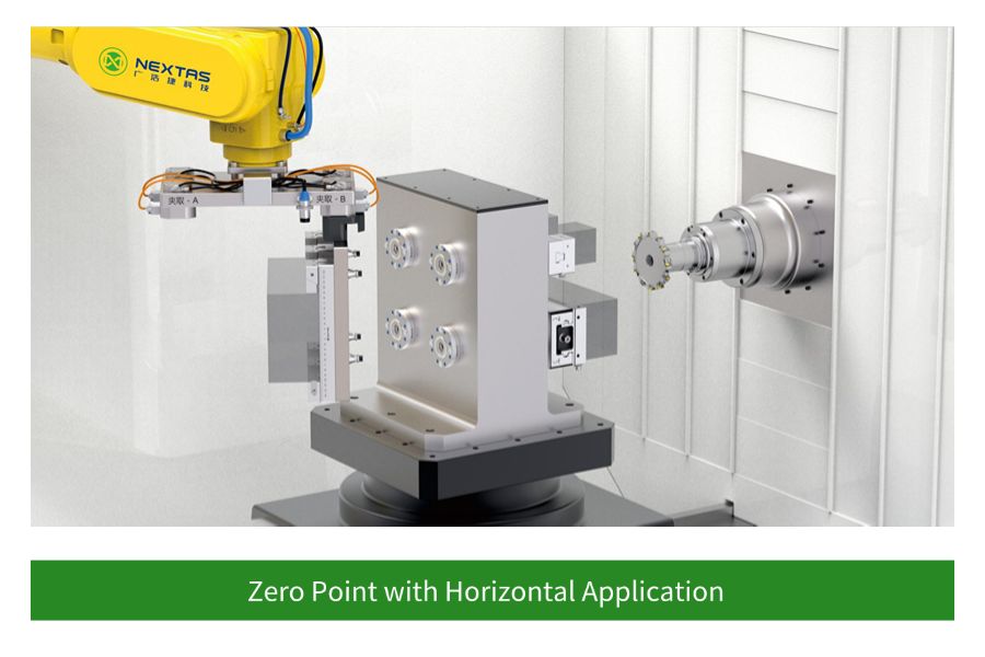
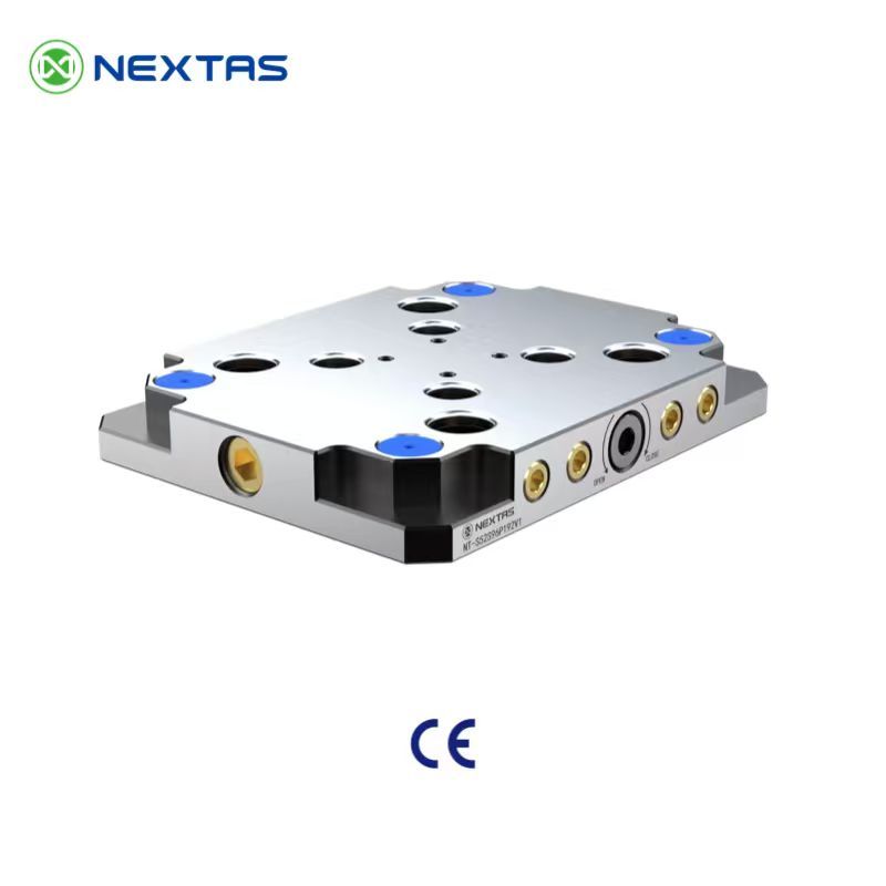
Core Locking Technology
Zero-Point Clamping Systems
Receiver modules and combination blocks for quick-change machining, pallet flow, and automation integration
Choose this page when the real question is the locking interface itself. The MFG module family covers compact receivers, multi-station blocks, and control-ready options for shops that need stable repeatability plus a cleaner path into pallet transfer, APC, or robot-assisted workholding.
≤ 0.003 mm repeatability
Spring self-locking structure
Sensor & automation ready
Best fit
When the receiver module is the real project core
Use this route when the buyer is selecting pull studs, receiver spacing, air routing, and control feedback rather than just looking for a datum plate under an existing fixture.
Integration prep
What to send for a faster module recommendation
Provide pallet size, pull-stud standard, inlet preference, sensor or confirmation requirements, and whether the module will tie into APC, robot, or manual quick-change stations.
Jump in by task
Use the page as a selection tool, not just a long catalogue
Start with the section that matches the real engineering decision: choosing module size, planning connections, or setting maintenance expectations.
Selection focus
Compare module footprint, receiver spacing, pull-stud compatibility, and whether a single or multi-station block fits the pallet logic.
Integration focus
Check inlet routing, automation ports, sensor feedback, and how the module connects with APC, pallets, or robot loading.
Maintenance focus
Review cleaning air, seating checks, and lock-state confirmation that protect repeatability in daily production.
Fast engineering handoff
Send the interface requirements first
- Pallet or fixture size and weight range.
- Pull-stud standard and preferred receiver spacing.
- Bottom-inlet or side-inlet routing requirement.
- Need for sensors, APC linkage, or robot confirmation.
Best fit
Use this route when the receiver module itself is the buying decision
Best for projects centered on pull studs, receiver spacing, air routing, and lock-state confirmation across pallets, vises, or automation carriers.
Compare first
Decide module footprint, inlet routing, and feedback requirement first
Single receiver modules, combination blocks, and control-ready versions become easier to compare once those three constraints are locked.
Related path
Not every project starts with the same hardware layer
If the real need is table standardization or pallet logistics first, jump sideways before going deeper into this module page.
Technical SpecificationsMechanism DetailsSelection & Integration GuideQuality & Reliability You Can AuditAdvanced Manufacturing ApplicationsSelection • Integration • Maintenance Cheatsheet
Catalogue System Map
| Family | What it covers | Typical models / note |
|---|---|---|
| MFG zero-point positioning datum | Single receiver modules for direct pallet, vise, chuck, or fixture changeover. | NT-S200P85V1 / 120V1 / 160V1 / 195V1 |
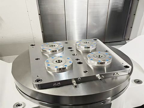
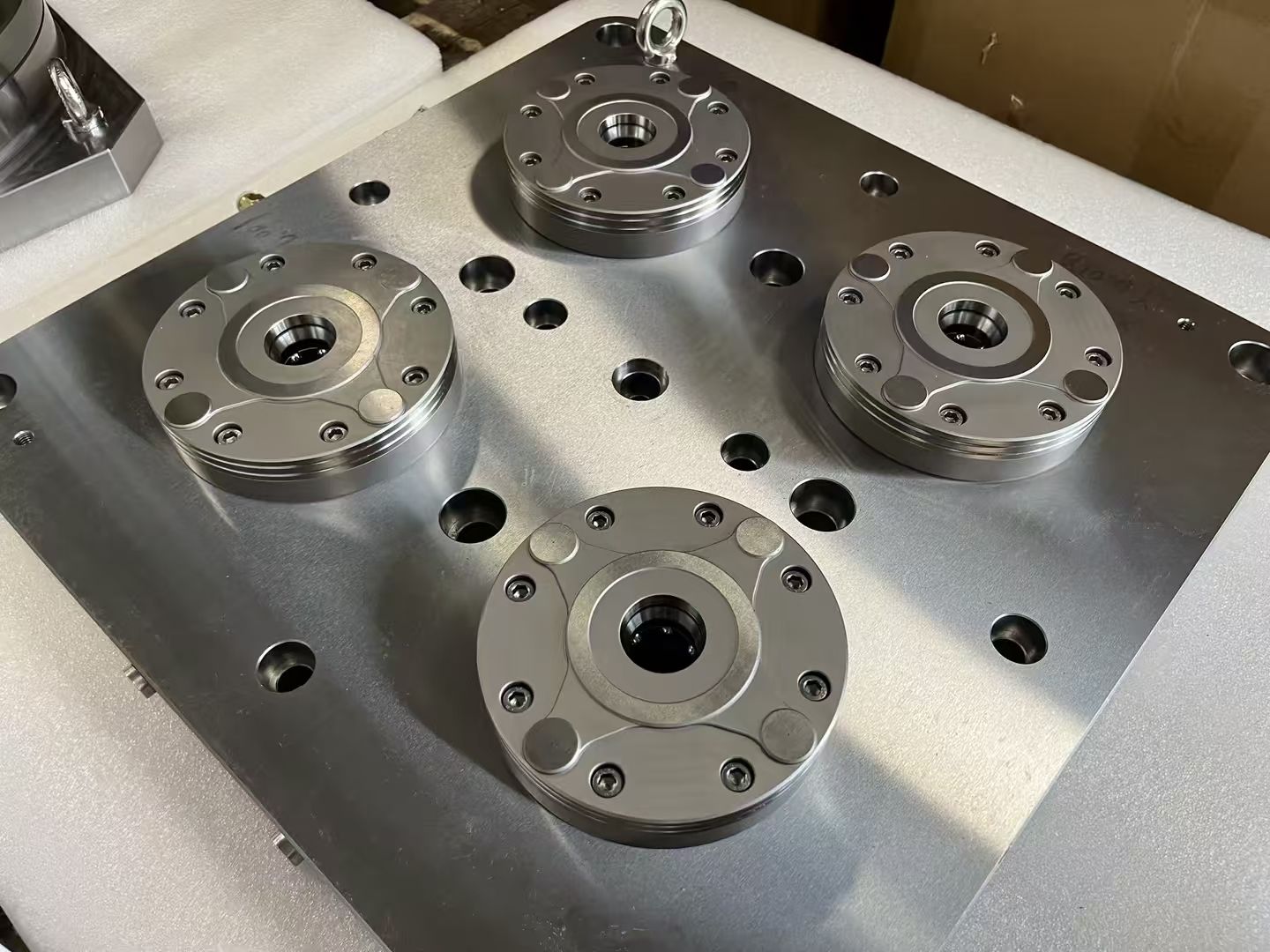
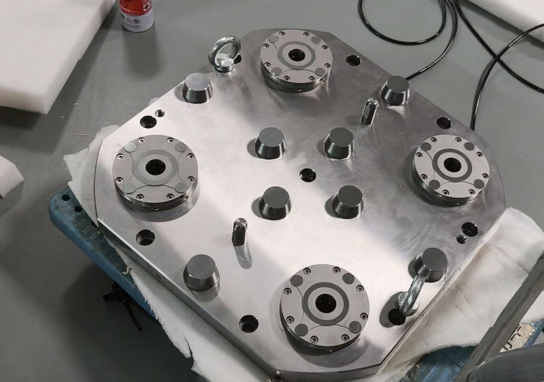
| MFG combination modules | Multi-station receiver blocks (2 / 4 / 6 stations) for larger pallets, tombstones, and automation-ready subplates, with auxiliary positioning modules (WJ2 / WJ4) for precise pallet indexing. | ZH2A/B, ZH4A/B, ZH6A/B on P120 or P160 base — e.g. NT-S200P120ZH2A through NT-S200P160ZH6B |
| Quick change datum plate family | Plate-level 52 mm / 96 mm foundations that standardize the machine interface. | See the zero-point clamping plate page for full 52 / 96 plate model matrix. |
| BDS positioning datum | Compact datum family used when smaller positioning interfaces are preferred in automation cells. | See the dedicated BDS page for A024 / B024 datum and pallet variants with <0.003 mm repeatability and 60,000 N clamping force. |
| Zero-point couplings | Quick EOAT / robot-side transfer interface for lightweight pallets, docking modules, and automation handoff. | NT-S600P90V1 coupling body with matching NT-S200P25 / 30 / 35 / 40 spigot family. |
| Sensor zero-point quick change datum | Receiver formats prepared for clamp / unclamp status confirmation in automated cells. | Used when PLC confirmation, robot interlock, or unattended cycle validation is required. |
Need the compact datum family?
BDS is now broken out as its own product detail page so engineers can review A024 / B024 datum bodies, matching pallets, clamping force, and handling notes without digging through the general zero-point overview.
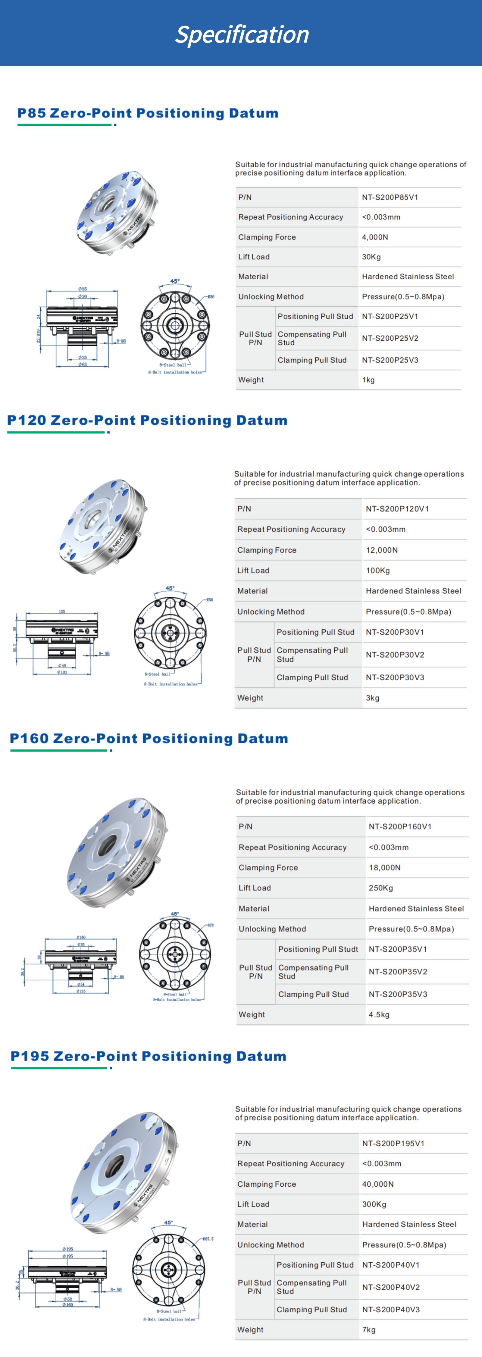
Technical Specifications
| Model | Module Diameter | Clamping Force | Lift Load | Repeatability |
|---|---|---|---|---|
| V1 — Standard pneumatic receivers (pressure-unlock, taper-type positioning) | ||||
| NT-S200P85V1 | 85 mm | 4 kN | 30 KG | ≤0.003 mm |
| NT-S200P120V1 | 120 mm | 12 kN | 100 KG | ≤0.003 mm |
| NT-S200P160V1 | 160 mm | 18 kN | 250 KG | ≤0.003 mm |
| NT-S200P195V1 | 195 mm | 40 kN | 300 KG | ≤0.003 mm |
| V2 — Compact pneumatic receivers (reduced stack height for integrated pallets and fixtures) | ||||
| NT-S200P85V2 | 85 mm | 5 kN | — | ≤0.003 mm |
| NT-S200P115V2 | 115 mm | 10 kN | — | ≤0.003 mm |
| NT-S200P148V2 | 148 mm | 18 kN | — | ≤0.003 mm |
Common Specifications (All Models)
- Actuation:Pneumatic unlocking (6 bar class supply, confirm your local air standard)
- Body Material:Hardened stainless steel
- Core functions:Taper-type positioning, mechanical self-locking, self-cleaning locating datum, air-tightness testing, and inner-hole cleaning.
Receiver family depth buyers often miss
The catalogue does not stop at four single receivers. It also shows multi-station receiver blocks, robot couplings, and sensor-ready formats that matter when the real project is pallet standardization or automated handoff.
| Receiver format | Where it fits best | Catalogue reference |
|---|---|---|
| Single receiver modules | Compact vises, 5-axis fixtures, smaller pallets, and machine-to-machine transfer where low stack height matters. | NT-S200P85V1 / P120V1 / P160V1 / P195V1 (and V2 compact variants P85V2 / P115V2 / P148V2) |
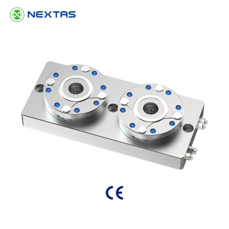
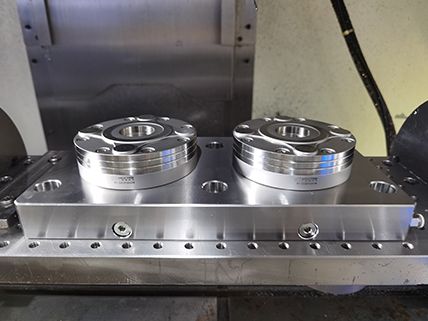
| Two-station combination modules | Longer pallets and subplates that need more support than a single receiver can provide. | NT-S200P120ZH2A / P120ZH2B / P160ZH2A / P160ZH2B · with auxiliary positioning modules NT-S200P120WJ2 / P160WJ2 |
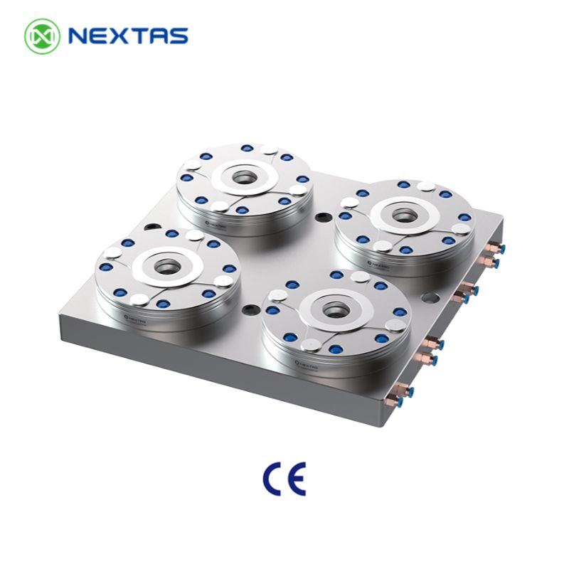
| Four-station combination modules | Larger pallets and subplates where four positioning points deliver higher support and stability. | NT-S200P120ZH4A / P120ZH4B / P160ZH4A / P160ZH4B · with auxiliary positioning modules NT-S200P120WJ4 / P160WJ4 |
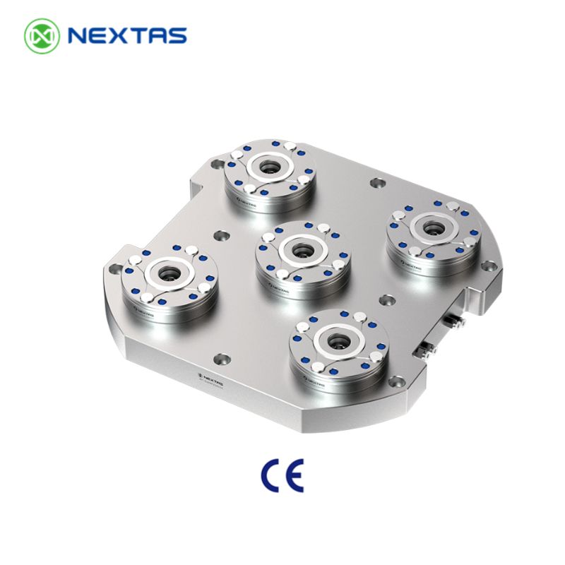
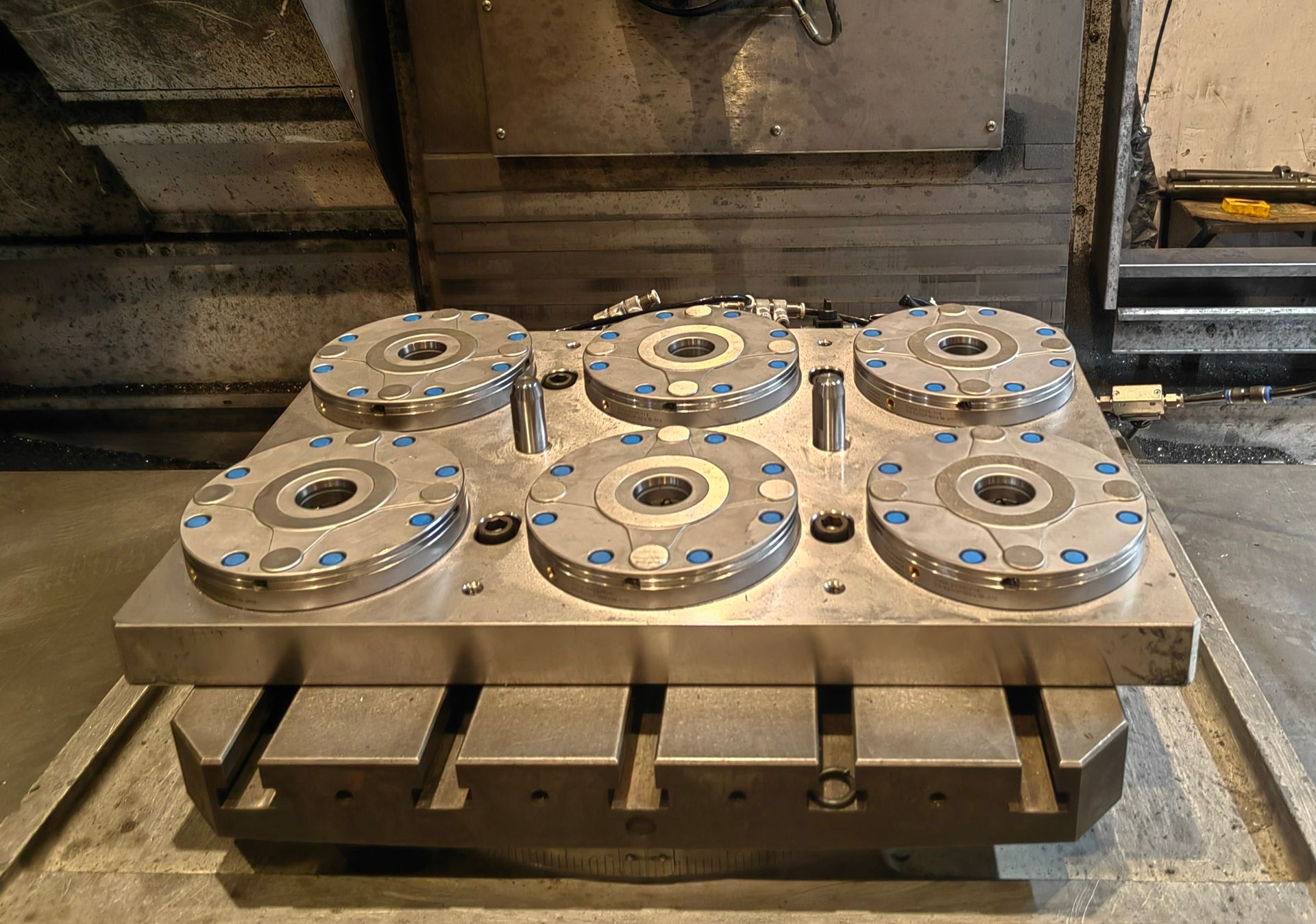
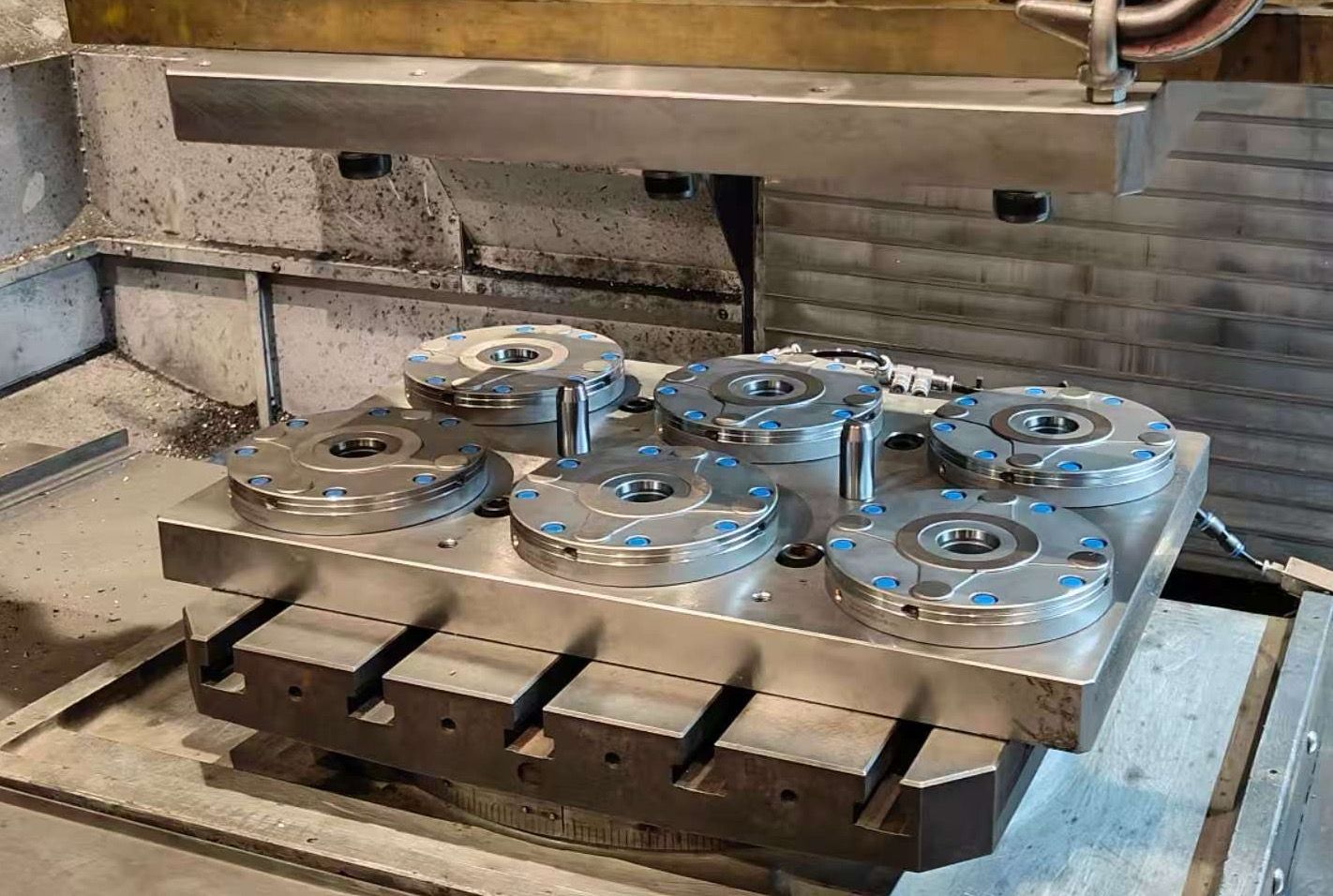
| Six-station combination modules | Tombstone layouts, large automated carriers, and pallet formats that demand six supported points. | NT-S200P120ZH6A / P120ZH6B / P160ZH6A / P160ZH6B |
| Zero-point couplings | Robot or transfer-side quick exchange where compact automation interface matters more than machine-table footprint. | NT-S600P90V1 + coupling pallet NT-S200P35TP01 |
| Sensor-ready zero-point interfaces | Cells that require clamp confirmation before pallet motion, robot pickup, or unmanned restart. | Sensor zero-point quick change datum family |
Mechanism Details
How the Mechanical Locking Works
Nextas Zero-Point modules are built from high-grade, hardened alloy steel for rigidity and long service life. The locking mechanism uses pneumatic pressure (typically 6 bar) to overcome powerful springs for unlocking. When the air is removed, these springs pull in and lock the clamping stud, creating a secure, vibration-proof connection that maintains its force even if air pressure is lost.
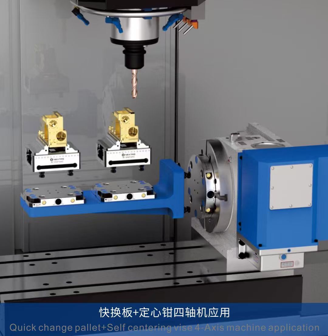
System in Action: Quick Changeover
This demonstration shows how the Zero-Point Clamping System enables fast pallet changes. The locking mechanism holds precision positioning within <0.003mm and allows complete changeovers in seconds.
(7)%20(1).png?updatedAt=1754553736043)
Bottom Inlet Solution Features
- • Flexible taper fit positioning · Repeatable positioning accuracy <0.003mm.
- • High-precision ball lock self-locking structure for proven stability.
- ③⑥ Pneumatic boosting function enhances clamping force.
- ④⑦ Air-tightness testing and surface self-cleaning function.
- ⑤⑧ Pneumatic lock/unlocking and chuck lifting function.
- • Jet cleaning function inside the pull stud hole prevents debris.
- • Air-tightness testing and positioning surface self-cleaning.

Key System Functions
- Mechanical Self-Locking: Maintains 100% clamp force even if air pressure is lost.
- Clamping Force Booster: Optional turbo function increases holding force for heavy-duty jobs.
- Self-Cleaning Air Blast: Integrated channels clear debris before clamping for perfect seating.
- Position Monitoring: Sensor-ready for feedback to confirm clamp/unclamp status for secure automation.
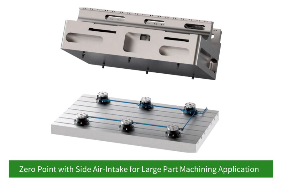
Flexible Intake Solutions
Choose bottom-inlet routing when you can bring air through the table or subplate and want the cleanest, best-protected layout. Choose side-inlet routing when retrofit access, hose serviceability, or machine constraints make lateral connection the more practical solution.
(7).png?updatedAt=1754553737609)
Selection & Integration Guide
How to specify a zero-point system for your machine
- Define your changeover goal: pallet swaps, fixture swaps, or both. This sets the receiver count and pallet strategy.
- Select receiver size: based on fixture weight, cutting load, and available footprint (85 / 120 / 160 / 195 mm options).
- Choose pull studs: standard vs. compact vs. anti-rotation, depending on clearance and datum requirements.
- Plan the sub-plate: optimize receiver spacing for tool access, chip flow, and coolant drainage.
- Decide air routing: bottom inlet for clean through-table plumbing; side inlet when through-table routing isn’t possible.
- Automation readiness: add clamp/unclamp confirmation sensors for APC/robot cells and safe PLC sequencing.
Typical retrofit paths
Zero-point systems pay off fastest when you standardize one interface across multiple setups. Here are the most common upgrade routes we support.
3-axis CNC → quick-change fixtures
Mount a receiver pattern on a sub-plate and add pull studs to your vises/fixtures. Great for mixed-batch work and short runs.
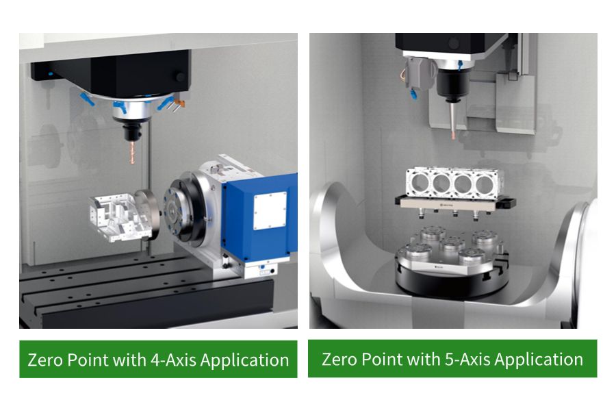
5-axis CNC → compact, high-access fixturing
Use dense receiver layouts and low-profile fixtures to maximize tool access and reduce re-indicating between operations.
Automation cell → pallet pool / APC / robot
Add clamp confirmation signals and consistent pallets to enable safe unattended changeovers and higher spindle uptime.
Receiver sizing & layout quick guide
These guidelines help early-stage planning for a quick-change pallet / fixture interface. Final selection depends on cutting loads, moments, and machine constraints — share your setup and we’ll propose a layout.
| Use case | Typical payload | Recommended receiver | Typical receiver count | Notes |
|---|---|---|---|---|
| Compact 5-axis fixtures / vises | ≤ 30 kg | 85 mm | 3–4 |
|
| General 3-axis quick-change setups | ≤ 100 kg | 120 mm | 4 |
|
| Heavy-duty fixtures / tombstones | ≤ 250 kg | 160 mm | 4–6 |
|
| Large pallets / automation / APC | ≤ 500 kg | 195 mm | 6–8 |
|
Bottom inlet vs. side inlet routing
| Option | Best when | Plumbing notes | Automation notes |
|---|---|---|---|
| Bottom inlet | You can route air through the table/sub-plate for a clean, protected setup. |
|
|
| Side inlet | Through-table routing isn’t possible, or you need a fast retrofit on existing plates. |
|
|
Quality & Reliability You Can Audit
For zero-point workholding, repeatability isn’t just a spec — it’s the result of material control, precision grinding, and functional testing. Nextas focuses on stable long-term performance in real chip-and-coolant environments.
Materials & wear resistance
- Hardened, corrosion-resistant steel on critical locating/locking interfaces.
- Precision-ground engagement surfaces to keep repeatability stable over cycles.
- Designed for coolant exposure with robust sealing and debris management.
Functional testing
- Air-tightness and actuation verification for consistent enable behavior.
- Self-cleaning air blast paths to protect seating accuracy in chip-heavy jobs.
- Repeatability validation guidance available for incoming inspection and FAT.
Support & documentation
- CAD/STEP files on request for fast fixture design and simulation.
- Configuration proposal with receiver spacing, porting plan, and BOM suggestions.
- Spare parts and maintenance checklist to keep uptime predictable.
Advanced Manufacturing Applications
Offline Setup & Palletization
Build fixtures and mount workpieces on pallets while the machine is running, drastically increasing machine uptime.
Multi-Machine Standardization
Use the same setup across multiple machines (3-axis, 5-axis, CMMs) for ultimate flexibility and reduced fixture inventory.
Full Automation Integration
Built-in sensing and pneumatic control provide the feedback needed for robotic pallet changers and unmanned cells.

5-Axis and Complex Machining
The compact modules allow for creative fixturing with minimal interference, providing maximum tool access.
Case Studies
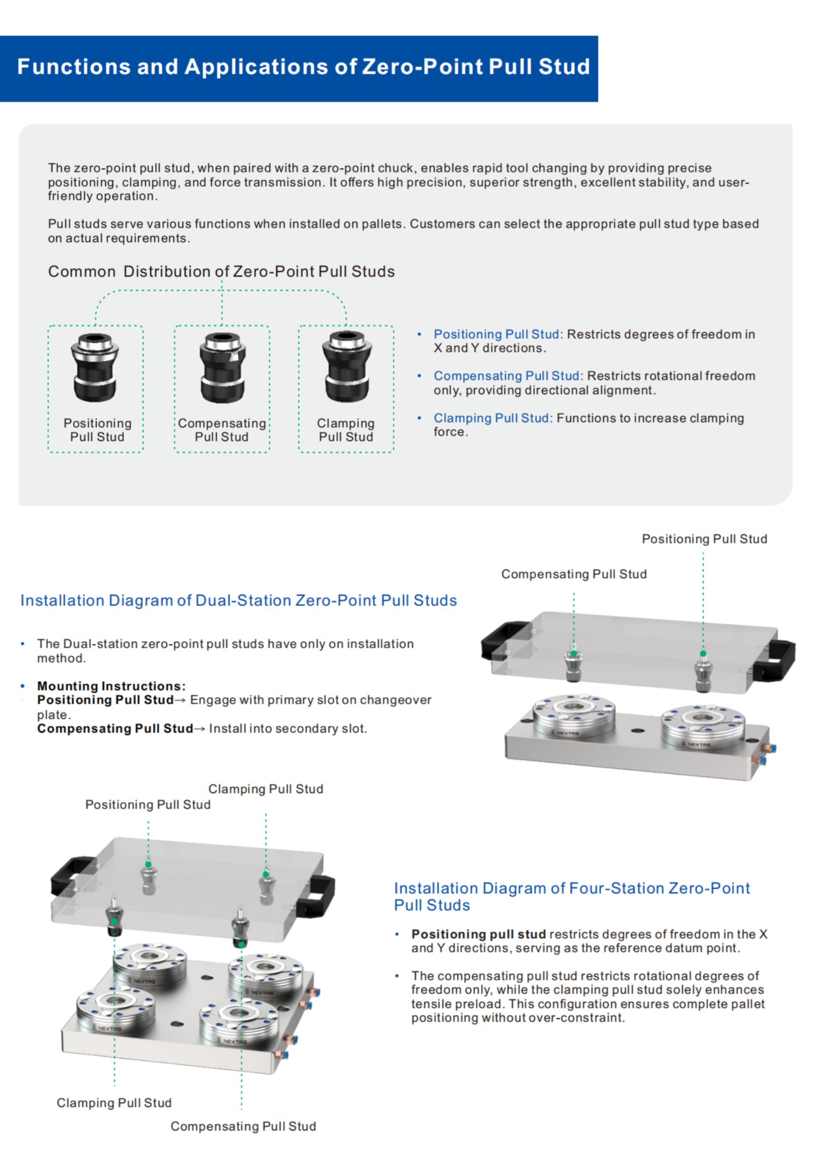
Dual-Station Zero-Point Clamping System


Four-Station Zero-Point Clamping System
Six-Station Zero-Point Clamping System
Choose the right zero-point architecture first
Most changeover problems are solved earlier when receiver layout, inlet routing and pallet strategy are matched to the machine and workpiece family before fixture design is frozen.
Single receiver modules
Best for compact fixtures, 5-axis work, vises or pallets that need a low-profile interface and straightforward maintenance access.
Combination blocks
A stronger starting point when one fixture needs multiple clamping points, higher support stiffness or a denser palletized layout.
Bottom inlet vs side inlet
Choose bottom inlet when through-table routing is available and protection is the priority. Choose side inlet when retrofit access or utility routing makes lateral connection more practical.
What to send for a safe module recommendation
Machine & footprint
Machine table, available mounting area, stack-height limit and whether the setup is 3-axis, 4-axis or 5-axis.
Fixture & load
Fixture mass, workpiece family, roughing severity and whether the setup must move between machining and inspection.
Utility routing
Tell us whether air can come through the table, through a sub-plate or only from the side so inlet selection stays practical.
Automation target
Share changeover time goals, pallet count, robot handoff requirements and the clamp/unclamp confirmation signals you need.
Selection • Integration • Maintenance Cheatsheet
A compact, shop-floor reference to help you choose the right configuration, integrate cleanly with your machine/automation, and keep repeatability stable in daily production.
1) Selection: pick the right configuration
| If you care most about… | Start with… | Why this helps |
|---|---|---|
| Fast changeovers / high-mix jobs | Standardize one interface (zero-point / ITS / 3R) across machines + build fixture plates/pallets. | Enables offline setup and swaps in seconds with minimal re-indicating. |
| 5-axis access and tool clearance | Choose low-profile components and plan clearance early (stack height, clamp body, wrench access). | Avoids collisions and preserves reach for deep features. |
| Lights-out / robot-tended machining | Add confirmations (clamp-OK / part-present), chip protection, and a recovery sequence. | Reduces mis-load risk and improves automation reliability. |
| Heavy roughing / high cutting forces | Increase support points and rigidity (more clamping stations, stiffer base, shorter stack-up). | Minimizes deflection and protects surface finish. |
2) Integration: what to prepare before install
| Item | Typical choice | Practical tip |
|---|---|---|
| Mounting and datums | Bolt pattern + dowel pins / keyways / reference edge | Define a master datum and keep a gauge pallet/part for quick verification. |
| Utilities | Clean, dry air with FRL; stable pressure; (hydraulic/electrical if used) | Drain FRL regularly and avoid long, restrictive hoses that slow actuation. |
| Control handshake | M-codes/PLC I/O: clamp, unclamp, clamp-OK, fault | Use timeouts + safe states; log signals to diagnose intermittent downtime. |
| Process validation | Probe macro / indicator check / first-article routine | Baseline repeatability after installation, then compare weekly. |
3) Maintenance: keep repeatability stable
| Risk / wear point | Early symptom | Prevention / quick fix |
|---|---|---|
| Chips on locating surfaces | Parts shift, repeatability drifts | Air-blow + wipe seating faces; add chip covers/air blast if needed. |
| Seals/wipers and sliding surfaces | Slow actuation, leaks, inconsistent clamp | Inspect on schedule; keep coolant/abrasives out; replace wear items proactively. |
| Loose fasteners / damaged contact faces | Unexpected misalignment, vibration marks | Torque-check; use dowels; stone minor nicks (don’t ‘machine’ the datum). |
| Contaminated air/oil | Sticky motion, alarms in automation | Improve filtration, dry air, drain bowls; keep a simple spare-kit. |
Need CAD/STEP, a mounting pattern, or a recommended setup for your part?
Contact usProduct Data & Evaluation Checklist
Use this checklist to validate repeatability, pull-down force, and automation fit during supplier evaluation.
Key specifications
| System components | Receiver modules + pull studs + mounting plate/pallet (configurable) |
|---|---|
| Repeatability | Typical targets down to ≤ 0.003 mm (application-dependent) |
| Locking concept | Fail-safe mechanical locking; pneumatic/hydraulic release options |
| Changeover focus | Quick fixture/pallet swaps for 3-axis & 5-axis machining |
| Wear surfaces | Hardened interfaces on critical locating and locking areas |
| Options | Manual / pneumatic / hydraulic, multiple receiver sizes & stud patterns |
Tip: share your part material, machine model, and target takt time. We’ll propose the right configuration and measurable targets.
Compatibility & standards
- Integrates with pallets, tombstones, vises, chucks, and custom fixtures.
- Layout can be designed for clearance, chip flow, and coolant access.
- Suitable for APC/robot cells with clamp confirmation and safe sequencing.
Measured outcomes (before → after)
- Setup time: minutes or seconds instead of manual re-indicating (process dependent).
- Stable datum after re-clamp: reduced probing time between operations.
- Lower scrap: fewer mis-location and tilt-related issues on multi-op jobs.
Workholding configuration
- BOM definition: receiver quantity, stud type, mounting hardware, porting (if applicable).
- Locator strategy: datum faces, pull-down direction, anti-rotation features.
- Fixture stack-up: plate/pallet → receiver → fixture/vice/chuck → part (verify rigidity).
Evidence & proof
- Fixture layout drawing (PDF/CAD snippet) showing receiver spacing and datum scheme.
- On-machine photos/videos of clamp/unclamp and pallet swap sequence.
- Inspection excerpt: re-clamp repeatability or probing repeat test (sample available).
Delivery & support
- Configuration proposal within 24–48h after receiving part info and machine constraints.
- Spare parts support: studs, seals, receiver components; maintenance checklist included.
- Optional FAT video before shipment for key assemblies.
Frequently Asked Questions
How does the 'fail-safe' mechanical locking work?
Our zero-point system uses powerful pre-loaded springs as the primary locking mechanism. Clamping is mechanical and constant. Pneumatic pressure (typically 6 bar) is used to enable. If air pressure is lost, your workpiece remains secured — ideal for unattended machining and automation.
What is the difference between the 'Bottom Inlet' and 'Side Inlet' solutions?
Bottom inlet routes air through the machine table or sub-plate for a clean, protected installation. Side inlet is a flexible option when through-table routing isn’t possible — air lines connect from the side of the module.
Can these modules be used for applications other than CNC machining?
Yes. We commonly see zero-point receivers used on CMM inspection stations, welding fixtures, assembly lines, and EDM processes — anywhere that repeatable positioning and fast changeover improve throughput.
What maintenance is required for the zero-point modules?
Keep the seating area clean, inspect periodically, and apply light lubrication as specified in the manual. In chip- and coolant-heavy environments, routine wipe-down and occasional leak checks help keep unlocking and seating consistent over time.
How do I integrate the system for automated position monitoring?
Automation-ready modules can be configured with sensor ports for proximity sensors that provide clamp/unclamp confirmation. This feedback can be wired to a PLC or robot controller to validate system status before an automated cycle starts.
How do I choose the right module size (85 / 120 / 160 / 195 mm)?
Start with pallet/fixture footprint, part and fixture weight, and cutting loads. Smaller receivers fit compact 5-axis fixtures and dense layouts; larger diameters provide higher load capacity and stiffness for heavier pallets, tombstones, and roughing. Share your table size and changeover goal and we can recommend a safe configuration.
Which pull stud should I use, and how important is stud quality?
The pull stud is the precision interface between your fixture and the receiver, so it impacts repeatability and wear. Choose the style based on clearance, fixture thickness, and whether you need anti-rotation. Precision-ground studs with consistent hardness and surface finish help keep repeatability stable over many cycles.
What air quality / filtration is recommended for stable long-term operation?
Use clean, dry air at the specified unlocking pressure (typically 6 bar). A filter-regulator or FRL unit helps protect seals and keeps unlocking consistent. Stable air quality is especially important for automated cells and repeatable unclamp timing.
Can I retrofit an existing fixture or vise to a zero-point system?
Yes. Many customers retrofit vises, chucks, and custom fixtures by adding pull studs to an adapter plate or the fixture base. The key is maintaining a stable datum scheme (flatness and bolt pattern) and providing chip/coolant clearance so the system seats cleanly every time. Send us your fixture drawing and we’ll propose a practical retrofit approach.
Resources & Downloads
Complete Your System
Zero-Point Clamping Plates
The ideal foundation. Our plates come with modules pre-installed for easy setup on any machine.
View Details →
BDS Positioning Datum
A compact datum and pickup interface when smaller carriers or robotic handoff points must stay standardized.
View Details →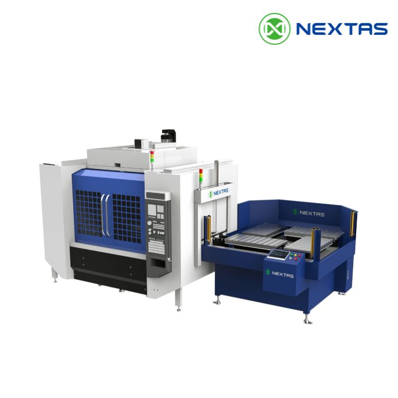
Automatic Pallet Changer
Maximize machine uptime with a fully integrated system built around our core technology.
View Details →