Enter your email address to request the brochure. Due to time zone differences, we’ll email it the next business morning (GMT+8, Beijing Time).
Automation Clamping Solution
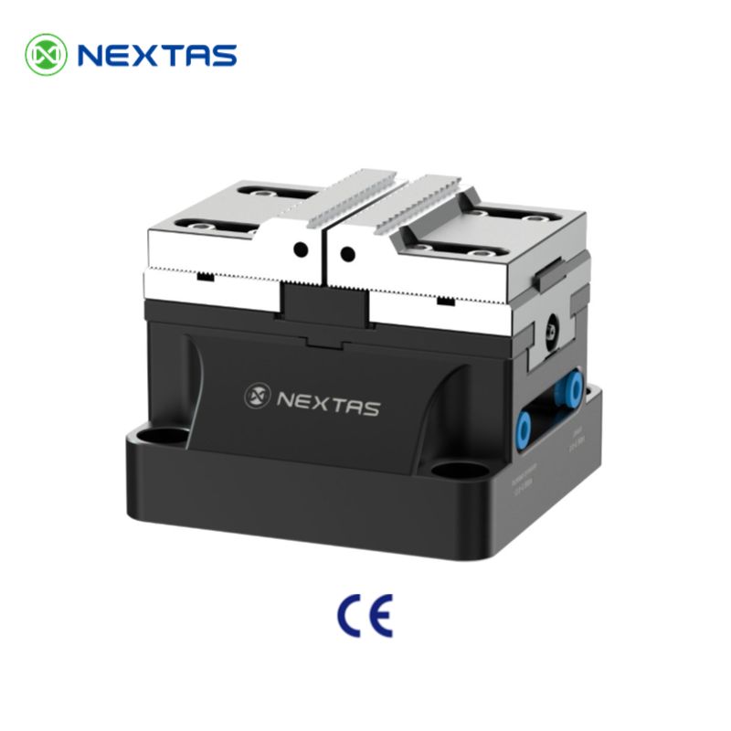
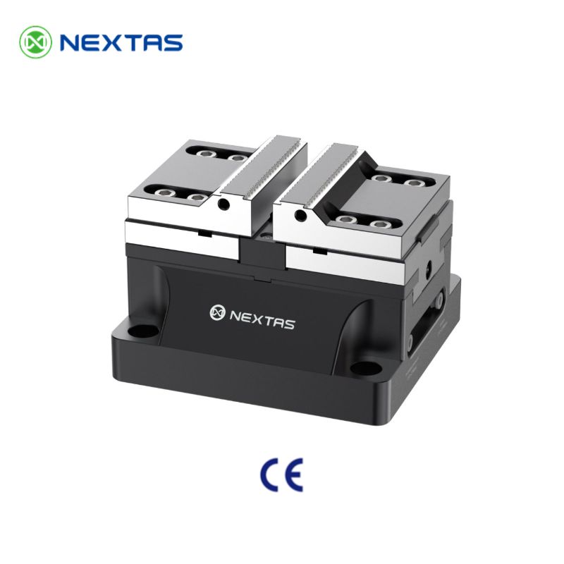
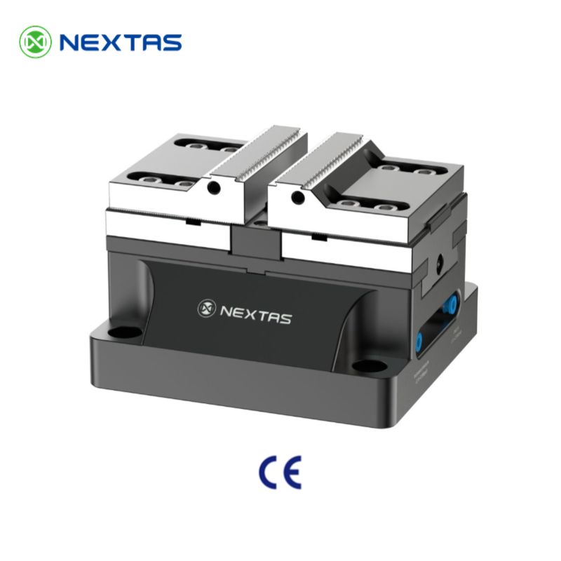
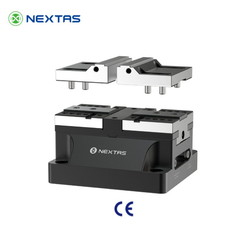
Pneumatic Self-Centering Vise for CNC Automation Cells
P75 / P110 / P150 workholding for repeatable clamping, faster cycle timing, and pallet-ready automation.
The Nextas pneumatic centering vise family covers P75, P110, and P150 so you can size the workholding around part range, clamping force, and automation flow before the fixture concept is locked. Start by choosing the body size, then confirm air or hydraulic actuation, jaw strategy, and pallet or zero-point integration.
P75 / P110 / P150 sizes
Pneumatic or hydraulic actuation
Robot + pallet integration path
Best fit
Choose this route when clamp timing and repeatability must stay stable in automated loading
A practical match for robot-loaded CNC cells, palletized workholding, and repeat jobs that need faster clamp / unclamp flow than manual vises can provide.
Compare first
Decide body size and actuation before going deep into jaw details
That sequence usually resolves the real question faster: compact cell vs heavier cut, air-only simplicity vs hydraulic force, and whether the vise should sit on a pallet or zero-point base.
Jump in by task
Use the page as a sizing and integration tool
Go straight to the section that matches the current job: comparing sizes, planning automation I/O, checking maintenance discipline, or downloading reference material.
Sizing focus
Compare P75, P110, and P150 against part range, jaw width, and the rigidity required for roughing or high-mix repeat work.
Automation focus
Check clamp / unclamp control, confirmation signals, air quality, and how the vise will sit on pallets or quick-change systems.
Process focus
Review jaw strategy, pressure setting, and the maintenance habits that keep repeatability stable during unattended production.
Fast engineering handoff
Send the cell and part-family details first
- Part range, material, and expected cutting load.
- Need for air-only simplicity or higher-force hydraulic actuation.
- Robot loading, pallet, or zero-point base integration plan.
- Signal confirmation, pressure range, and uptime target.
Key Technical SpecificationsPowerful and Versatile ApplicationsSelection & Automation Integration GuidePneumatics, Setup & MaintenanceReal-World Case StudiesSelection • Integration • Maintenance Cheatsheet
Catalogue model matrix
P75 / P110 / P150 Specifications
The catalogue lists three self-centering vise sizes with pneumatic and hydraulic variants, making it easier to shortlist by workpiece envelope, cutting load and available machine space instead of forcing a one-size-fits-all choice.
| Model | Product code | Actuation | Working pressure | Repeatable clamping accuracy | Clamping force | Adjustment range | Weight |
|---|---|---|---|---|---|---|---|
| P75 | NT-S75P75V1 | Pneumatic | 0.5–0.8 MPa | <0.01 mm | 4,200 N | 0–125 mm | 7 kg |
| P75 | NT-S75P75V2 | Hydraulic | 6 MPa | <0.01 mm | 9,000 N | 0–125 mm | 7 kg |
| P110 | NT-S110P110V1 | Pneumatic | 0.5–0.8 MPa | <0.01 mm | 12,000 N | 0–200 mm | 24.9 kg |
| P110 | NT-S110P110V2 | Hydraulic | 6 MPa | <0.01 mm | 30,000 N | 0–200 mm | 24.9 kg |
| P150 | NT-S150P150V1 | Pneumatic | 0.5–0.8 MPa | <0.01 mm | 20,000 N | 0–250 mm | 41.6 kg |
| P150 | NT-S150P150V2 | Hydraulic | 6 MPa | <0.01 mm | 45,000 N | 0–250 mm | 41.6 kg |
Use P75 for compact blanks
Best for smaller parts, tighter robot access, or machines where table space is limited.
Use P110 for the middle ground
A good fit for general CNC production where you need more range and force without jumping to the heaviest body size.
Use P150 for heavier cuts
The largest family is the right starting point for larger workpieces, stronger roughing loads, and more demanding automation cells.
How to shortlist the right size
- P75: compact blanks, tighter robot access and machines where table space is limited.
- P110: the middle-ground choice for general CNC production, mixed part families and balanced force requirements.
- P150: larger workpieces, stronger roughing loads and automation cells that need the highest rigidity in this family.
Powerful and Versatile Applications
Automated Machining Cells
Perfect for robotic arm loading/unloading systems, enabling long periods of stable, unmanned production.
Mass Production of Parts
Provides consistent clamping in automotive and electronics, ensuring quality and shortening cycle times.
Horizontal Machining Centers
Ideal for pallet changers, allowing multiple workpieces to be machined in a single setup.
Heavy-Duty Cutting Applications
Securely holds workpieces under high-feed, deep-cut conditions, perfect for tasks like mold roughing.
Application Fit Matrix
Use this matrix to decide where a pneumatic-hydraulic vise adds the most value—especially in lights-out machining, palletized systems, and robot loading.
| Scenario | Why it fits | Recommended add-ons |
|---|---|---|
| Robot-loaded VMC (high throughput) | Fast clamp/unclamp reduces idle time and keeps cycle timing consistent. | Clamp-OK confirmation (pressure/position), hard jaws, chip-blow air nozzle. |
| Palletized HMC / APC lines | Repeatable locating supports multi-op part families with minimal touch-off. | Zero-point clamping plate, standardized locating keys, quick-change jaw sets. |
| 5-axis / multi-side machining | Self-centering workholding simplifies symmetric parts and helps keep the datum stable. | Low-profile jaws, soft jaws bored in place, collision-safe jaw length limits. |
| High-mix, short runs | Quick changeovers + consistent clamping improves first-part success rate. | Pre-machined soft-jaw blanks, setup checklist, QR-labeled jaw library. |
| Interrupted cutting / mold roughing | Stable force helps resist chatter during heavy cuts and step-downs. | Higher pressure within spec, rigid hard jaws, coolant-resistant wipers. |
| Automotive & electronics mass production | Predictable clamping supports SPC and keeps dimensional drift under control. | Pressure regulator with lock, periodic verification gauge, spare seal kit. |
Selection & Automation Integration Guide
A practical checklist for choosing a pneumatic self-centering vise and integrating it into robotic CNC cells, pallet systems, and high-mix production—without sacrificing repeatability.
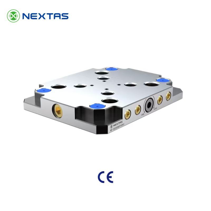
Need faster changeovers? Mount the vise on a zero-point clamping plate or a pneumatic zero-point plate to reduce setup time.
- Part family & jaw strategy: match jaw width/opening to your parts; use hard jaws for repeatable clamping and soft jaws for custom profiles (bore in-place for best concentricity).
- Clamping force vs cutting plan: validate force requirements for high-feed roughing, deep pockets, and interrupted cuts; consider the built-in pneumatic-hydraulic booster for stable force.
- Repeatability targets: protect ≤0.01 mm repeatability by keeping jaw seats clean, controlling torque, and standardizing locating surfaces across pallets/fixtures.
- Mounting & referencing: use keyways/bolt patterns for quick alignment; combine with palletized automation (HMC/APC) for lights-out operation.
- Automation I/O: design clamp/unclamp control with solenoid valves and add confirmation (pressure/position sensors) so the robot never loads on an unknown state.
Jaw Options & Part Strategy
Choose jaws based on how you want to locate the part (OD/ID, flats, or custom profile) and how often you will change part families.
| Jaw type | Best for | Tip |
|---|---|---|
| Hard jaws | Repeatable clamping in automation and pallet work | Keep seats clean; use locating keys to protect ≤0.01 mm repeatability. |
| Soft jaws (bore in place) | Custom profiles, thin walls, cosmetic surfaces | Bore at clamp pressure used in production to reduce spring-back errors. |
| Serrated / grip jaws | Rough blanks and heavy roughing | Use only where witness marks are acceptable; verify part pull-out risk. |
| V-block or prism jaws | Round stock (shafts, bushings, cylinders) | Pair with part-present sensing for reliable robot loading. |
| Fixture jaws / nests | Multi-part loading and takt-time optimization | Design for chip evacuation; avoid coolant pools that affect seating. |
Automation I/O & Safety Signals
A robot should never load/unload against an unknown clamp state. These are common signals used with an automation-ready pneumatic vise.
| Signal / component | Purpose | Typical implementation |
|---|---|---|
| Clamp command | Initiates clamp cycle | PLC output → solenoid valve (5/2 or 3/2), with exhaust silencer. |
| Unclamp command | Opens jaws for loading | Separate solenoid channel; interlock with door/E-stop. |
| Clamp-OK confirmation | Prevents cutting on partial clamp | Pressure switch or position sensor wired into CNC/robot permissives. |
| Air pressure monitoring | Detects regulator drift or supply loss | Regulator + gauge; optional transducer for trend monitoring. |
| Part-present sensing | Confirms blank is seated | Inductive/optical sensor or robot vision check before clamp. |
| Chip-blow / seat cleaning | Protects repeatability over long runs | Timed air blast + coolant management to keep jaw seats clean. |
Pneumatics, Setup & Maintenance
Stable air supply and basic housekeeping are what keep a pneumatic vise predictable in automation. Use this as a quick commissioning + upkeep checklist.
For process planning, see our guide: Pneumatic vise for CNC machining.
- Air quality: use clean, dry, filtered air (FRL). Keep air supply consistent to avoid cycle-to-cycle variation.
- Pressure setting: follow the recommended 5–7 bar range; place a regulator close to the machine to reduce pressure drop.
- Hose routing: keep lines short, avoid leaks, and consider quick exhaust where faster actuation helps throughput.
- Commissioning: run repeated clamp/unclamp cycles, verify jaw parallelism, and record clamp time as a baseline for future checks.
- Routine care: remove chips/coolant from sealing areas, inspect wipers/seals, and periodically verify repeatability with a gauge block or reference part.
Maintenance Schedule (Quick Planner)
Simple, consistent checks keep a pneumatic-hydraulic vise stable in unattended machining. Use this table as a shop-floor routine.
| Interval | What to do | Why it matters |
|---|---|---|
| Each shift | Blow off chips from jaw seats; quick visual check for leaks and loose fittings. | Prevents seating errors that ruin repeatability and part datums. |
| Weekly | Drain FRL bowl; confirm regulator setpoint; verify clamp-OK signal response. | Stops pressure drift that can cause inconsistent clamping force. |
| Monthly | Inspect jaw mounting faces; check keyways/bolts; clean exposed sliding surfaces. | Reduces jaw tilt/deflection and protects surface finish. |
| Quarterly | Verify repeatability with a simple gauge part; review automation logs for alarms. | Catches gradual wear before scrap accumulates in lights-out runs. |
| Annually | Preventive seal inspection; refresh booster oil if your service plan calls for it. | Extends service life and avoids sudden clamp-force loss. |
| After a crash | Recheck base flatness, jaw alignment, and sensor mounting; perform a clamp/unclamp test. | Restores geometry and prevents hidden errors from propagating. |
Real-World Case Studies
Selection • Integration • Maintenance Cheatsheet
A compact, shop-floor reference to help you choose the right configuration, integrate cleanly with your machine/automation, and keep repeatability stable in daily production.
1) Selection: pick the right configuration
| If you care most about… | Start with… | Why this helps |
|---|---|---|
| Fast changeovers / high-mix jobs | Standardize one interface (zero-point / ITS / 3R) across machines + build fixture plates/pallets. | Enables offline setup and swaps in seconds with minimal re-indicating. |
| 5-axis access and tool clearance | Choose low-profile components and plan clearance early (stack height, clamp body, wrench access). | Avoids collisions and preserves reach for deep features. |
| Lights-out / robot-tended machining | Add confirmations (clamp-OK / part-present), chip protection, and a recovery sequence. | Reduces mis-load risk and improves automation reliability. |
| Heavy roughing / high cutting forces | Increase support points and rigidity (more clamping stations, stiffer base, shorter stack-up). | Minimizes deflection and protects surface finish. |
2) Integration: what to prepare before install
| Item | Typical choice | Practical tip |
|---|---|---|
| Mounting and datums | Bolt pattern + dowel pins / keyways / reference edge | Define a master datum and keep a gauge pallet/part for quick verification. |
| Utilities | Clean, dry air with FRL; stable pressure; (hydraulic/electrical if used) | Drain FRL regularly and avoid long, restrictive hoses that slow actuation. |
| Control handshake | M-codes/PLC I/O: clamp, unclamp, clamp-OK, fault | Use timeouts + safe states; log signals to diagnose intermittent downtime. |
| Process validation | Probe macro / indicator check / first-article routine | Baseline repeatability after installation, then compare weekly. |
3) Maintenance: keep repeatability stable
| Risk / wear point | Early symptom | Prevention / quick fix |
|---|---|---|
| Chips on locating surfaces | Parts shift, repeatability drifts | Air-blow + wipe seating faces; add chip covers/air blast if needed. |
| Seals/wipers and sliding surfaces | Slow actuation, leaks, inconsistent clamp | Inspect on schedule; keep coolant/abrasives out; replace wear items proactively. |
| Loose fasteners / damaged contact faces | Unexpected misalignment, vibration marks | Torque-check; use dowels; stone minor nicks (don’t ‘machine’ the datum). |
| Contaminated air/oil | Sticky motion, alarms in automation | Improve filtration, dry air, drain bowls; keep a simple spare-kit. |
Need CAD/STEP, a mounting pattern, or a recommended setup for your part?
Contact usProduct Data & Evaluation Checklist
For automated clamping, validate clamp force consistency, booster behavior, and cycle stability over long runs.
Key specifications
| Vise type | Pneumatic vise with pneumatic or hydraulic actuation (model dependent) |
|---|---|
| Clamping | Consistent clamp force for repeat production |
| Automation fit | Ready for robot/APC workflows with repeatable actuation |
| Accuracy goal | Stable positioning suitable for production machining |
| Maintenance | Serviceable seals; accessible air/hydraulic service points |
| Options | Jaw sets, sensors, and custom mounting patterns |
Tip: share your part material, machine model, and target takt time. We’ll propose the right configuration and measurable targets.
Compatibility & standards
- Pairs with zero-point plates/pallets for fast automated changeovers.
- Suitable for CNC lines requiring consistent clamp/unclamp cycles.
- Sensor-ready options can provide clamp confirmation signals.
Measured outcomes (before → after)
- Cycle time: less manual handling and fewer clamp adjustments.
- Quality stability: reduced variation in clamping across shifts.
- Reduced rework: fewer clamp-related surface/position deviations.
Workholding configuration
- Define mounting: spigot standard or bolt pattern, plus clearance for air lines.
- Jaw plan: soft jaws for delicate parts vs serrated jaws for heavy cuts.
- Automation sequencing: clamp confirmation + safe release conditions.
Evidence & proof
- Cycle test log/video showing repeated clamp/unclamp stability.
- Clamp verification method (sample procedure) and inspection excerpt.
- Photos of integration with pallets/plates and line setup.
Delivery & support
- Commissioning support for booster tuning (where applicable).
- Spare seals and preventive maintenance checklist for high-cycle production.
- Optional acceptance video before shipment.
Frequently Asked Questions
What is High-Precision Pneumatic Vise and who is it for?
The High-Precision Pneumatic Vise is a powerful clamping device designed for automated CNC machining and mass production.
What are the key specifications of High-Precision Pneumatic Vise?
Jaw Width: 160 mm; Max Opening: 300 mm; Clamping Force (at 6 bar): 45,000 N on hydraulic models; Repeatability: ≤0.01 mm; Actuation: Pneumatic (Pneumatic-Hydraulic Booster); Recommended Air Pressure: 0.5–0.8 MPa (pneumatic) / 6 MPa (hydraulic)
Which machines or use cases is it compatible with?
It is compatible with CNC machining centers, milling machines, and can be integrated with ITS systems for automation.
How is it installed or mounted?
Installation is via standard keyways and mounting holes on T-slot tables. It also has pneumatic/hydraulic interfaces and locating pins for precise setup.
Where can I get CAD files or technical documentation?
If you need STEP/IGES or 2D drawings, please Contact us.
What are the advantages of your pneumatic vise compared to a traditional hydraulic vise?
A key advantage is that this vise family gives you both pneumatic and hydraulic choices in the same centering-vise format. That lets you balance plant utilities, target clamping force, and automation simplicity without changing the overall workholding concept.
What is the repeatability of this vise?
Catalog-listed P75 / P110 / P150 models are specified at <0.01 mm repeatable clamping accuracy, which supports consistent automated changeovers.
What is special about the FCD60 ductile iron body?
FCD60 is a high-tensile ductile iron. This material provides excellent rigidity and vibration-damping capabilities. During heavy-duty cutting, it effectively absorbs machining vibrations, ensuring stability, a superior workpiece surface finish, and extending the vise's long-term durability.
What air supply and control hardware do I need for automation?
Use clean, dry, filtered air (FRL) and keep pressure stable in the recommended 5–7 bar range. For robotic cells, drive clamp/unclamp via a solenoid valve (PLC/M-code) and add confirmation using pressure or position sensors.
How do I choose jaws (hard jaws vs soft jaws) for repeatable setups?
Use hard jaws for repeatable production clamping and soft jaws when you need a custom profile. For best accuracy, machine soft jaws in-place, keep jaw seats clean, and standardize jaw changeover torque and locating features.
Can I combine this pneumatic vise with a zero-point system for fast changeovers?
Yes. Mount the vise on a zero-point clamping plate or pallet to speed up fixture swaps and keep referencing consistent across machines—especially useful for HMC pallet systems and high-mix production.
What maintenance helps keep ≤0.01 mm repeatability over time?
Keep chips/coolant away from sealing and seating surfaces, inspect wipers/seals regularly, and verify repeatability with a gauge block or reference part. Record baseline clamp time/pressure so you can spot drift early.
Resources & Downloads
Related Products
Zero-Point Clamping Plate
Standardize the machine-side datum before adding pneumatic workholding to mixed CNC setups.
View Details →Pneumatic Zero-Point Plate
Combine machine-controlled clamp/unclamp with pneumatic vises when the full fixture stack must cycle automatically.
View Details →Automatic Pallet Changer
A strong next step once pneumatic clamping is standardized and the target shifts toward unattended pallet turnover.
View Details →