
Enter your email address to request the brochure. Due to time zone differences, we’ll email it the next business morning (GMT+8, Beijing Time).
5-Axis Machining Solution
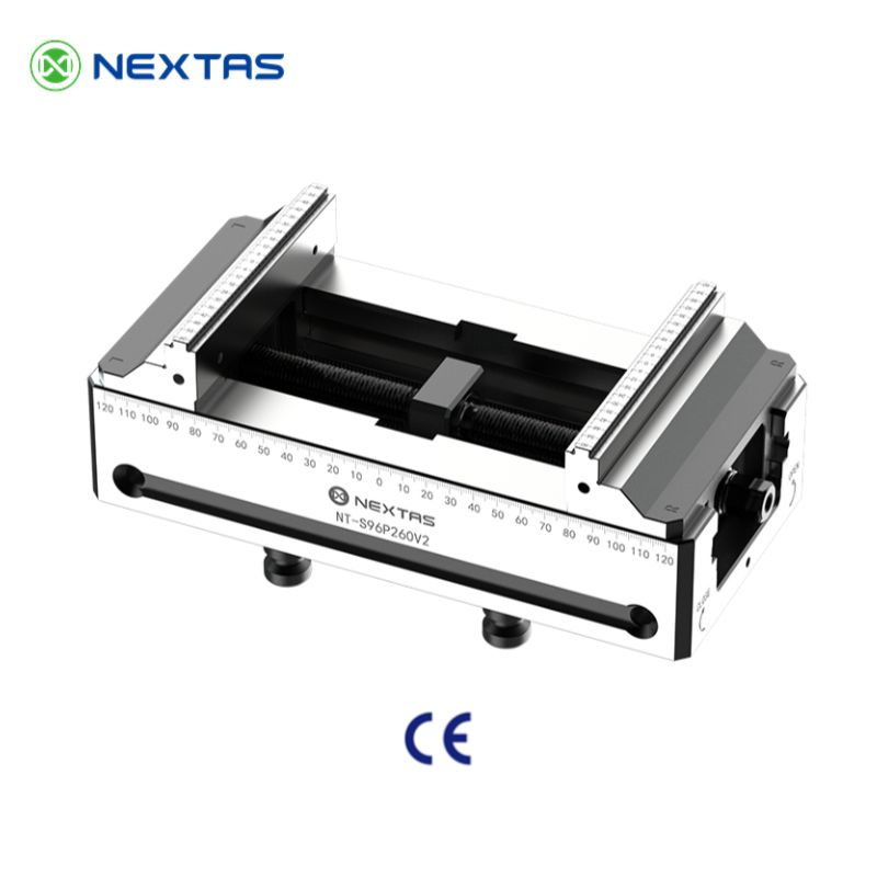
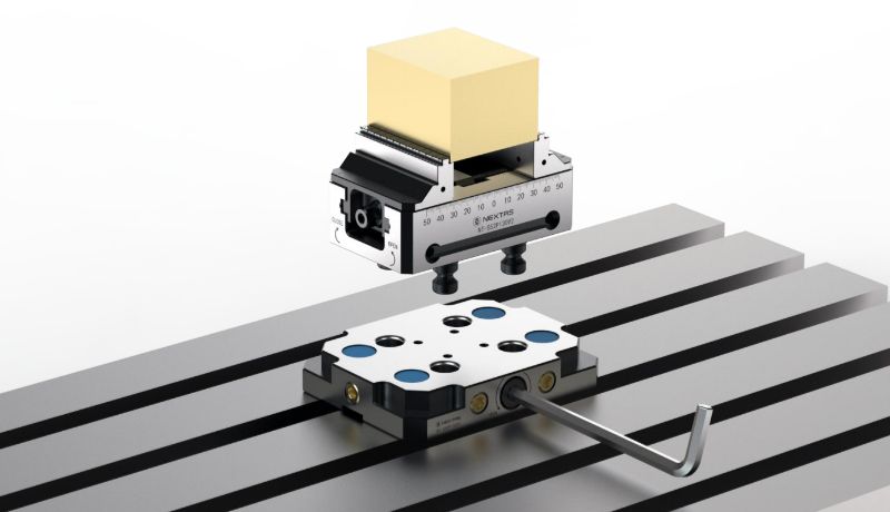
High-Precision 5-Axis Self-Centering Vise
52 / 96 mm modular vise family for 5-axis access, repeatable centering, and fast setup carryover
This series is built for shops that need centered holding, cleaner tool access, and predictable setup repeatability across mixed part sizes. Ideal when the vise needs to move between zero-point plates, pallets, or automated loading workflows.
< 0.02 mm
Repeatability
52 / 96 mm
Platform Size
14 / 20 kN
Clamping Force
Best fit
Use it when five-side access and centered holding outrank raw jaw width
A strong choice for aerospace, mold, and mixed-batch parts where centered grip, tool clearance, and repeat setup carryover all matter.
Compare first
Start with 52 / 96 mm platform, jaw strategy, and clamping range
Those three decisions usually resolve whether the vise fits the real part family before you dive into the full specification tables.
Go next
Jump to selection, integration, or downloads
Use the page like a decision tool rather than reading everything linearly from top to bottom.
Jump in by task
Start with the decision that matters most
The page below goes deep. These shortcuts help you start with selection, integration, or upkeep instead of scrolling through everything at once.
Selection focus
Match base size, jaw type, clamping range, and tool-clearance needs to the real part family.
Integration focus
Plan how the vise will sit on zero-point plates, pallets, or robot handoff routines without rebuilding the setup later.
Maintenance focus
Review jaw care, centering checks, and handling habits that keep repeatability steady through daily production.
Fast engineering handoff
Send the part and process constraints first
- Workpiece size range and material.
- Jaw type or special gripping concern.
- 5-axis clearance requirement and tool reach limits.
- Need for zero-point, pallet, or robot compatibility.
In-Depth Product DetailsTechnical DiagramsApplication Cases & SolutionsReal-World Case StudiesBuilt for ProductionSetup Guide & Best Practices
In-Depth Product Details
Learn how the engineering works behind our Self-Centering Vise.
Key Technical Specifications
| Family | Spigot Distance | Repeat Positioning Accuracy | Clamping Force | Maximum Torque | Material | Representative Models |
|---|---|---|---|---|---|---|
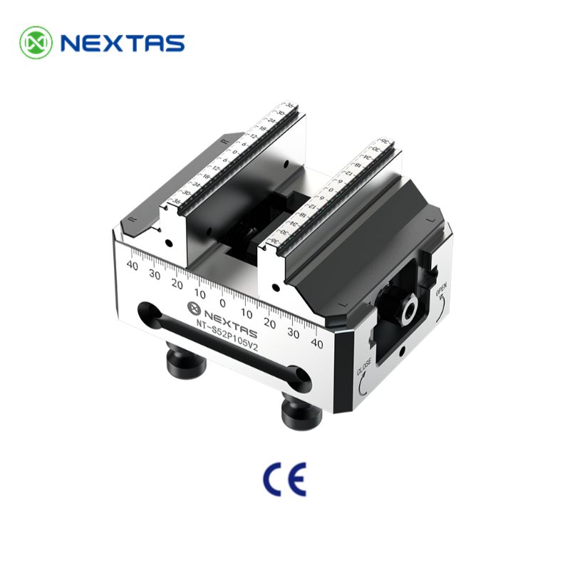
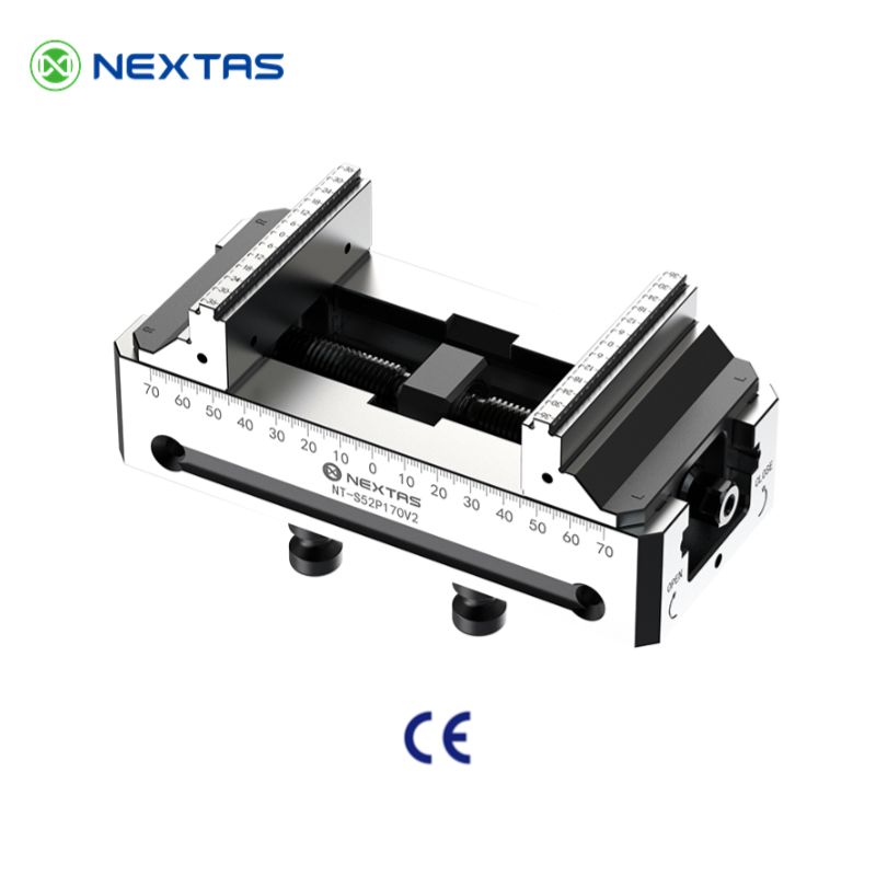
| 52 Self Centering Vise | 52 mm | <0.02 mm | 14,000 N | 70 Nm | Hardened stainless steel | NT-S52P105V2 / 130V2 / 170V2 / 210V2 |
| 96 Self Centering Vise | 96 mm | <0.02 mm | 20,000 N | 100 Nm | Hardened stainless steel | NT-S96P160V2 / 210V2 / 260V2 / 310V2 / 360V2 |
Catalogue Model Matrix & Clamping Range
The table below matches the 52 mm and 96 mm self-centering vise families shown in the catalogue, so buyers can compare footprint, clamping range, and shipping weight without switching back to the PDF.
| Product Code | Jaw Width | Overall Length | Height | Clamping Range | Weight |
|---|---|---|---|---|---|
| NT-S52P105V2 | 77 mm | 105 mm | 87 mm | 0 ~ 95 mm | 2.8 kg |
| NT-S52P130V2 | 77 mm | 130 mm | 87 mm | 0 ~ 120 mm | 3.2 kg |
| NT-S52P170V2 | 77 mm | 170 mm | 87 mm | 0 ~ 160 mm | 3.8 kg |
| NT-S52P210V2 | 77 mm | 210 mm | 87 mm | 0 ~ 200 mm | 4.4 kg |
| NT-S96P160V2 | 125 mm | 160 mm | 111 mm | 0 ~ 150 mm | 8.9 kg |
| NT-S96P210V2 | 125 mm | 210 mm | 111 mm | 0 ~ 200 mm | 10.8 kg |
| NT-S96P260V2 | 125 mm | 260 mm | 111 mm | 0 ~ 250 mm | 12.6 kg |
| NT-S96P310V2 | 125 mm | 310 mm | 111 mm | 0 ~ 300 mm | 14.5 kg |
| NT-S96P360V2 | 125 mm | 360 mm | 111 mm | 0 ~ 350 mm | 16.4 kg |
Jaw & Grip Strategy Matrix
Match jaw style to material, surface condition, and cutting load. The matrix below is a practical starting point for selecting jaws on a 5-axis self-centering vise (and for repeatable automation setups).
| Workpiece & material | Goal / operation | Recommended jaw & grip method | Why it works (notes) |
|---|---|---|---|
| Rough stock, castings/forgings (steel/iron) | Aggressive roughing, high torque | Serrated jaws + longer grip length | Serrations bite into scale; longer engagement improves stability on 5-axis tool access. |
| Aluminum / soft alloys (finished surfaces) | Finish milling with cosmetic surfaces | Machined soft jaws (custom pocket) | Pre-machined pockets distribute load and avoid jaw marks; great for high-mix CNC milling. |
| Thin-wall parts (rings, housings) | Minimize distortion while maintaining tolerance | Soft jaws + relief cut / support pads | Controlled contact area reduces deformation; probe a datum after clamping for repeatable offsets. |
| Round bar / shafts | Keep true centerline for 5-axis ops | V-jaws or V-blocks on soft jaws | Self-centers round stock and improves concentricity for multi-side machining. |
| Symmetrical prismatic parts | Fast changeovers, repeatable datum | Standard jaws + locating step / stop | A consistent stop surface improves part-to-part repeatability for pallet and robot loading. |
| Hard materials (tool steel, titanium) | Resist slip under heavy cuts | Serrated or hardened jaws + conservative depth of grip | Higher friction + safer grip depth lowers risk of micro-slip that shows up as tolerance drift. |
Repeatability Drivers & Quick Checks
Repeatability is a system result (interface + vise + jaws + process). Use the checks below to stay on track when you’re chasing tight tolerances on 5-axis workholding.
| Driver | Quick check | What it affects |
|---|---|---|
| Mounting interface (zero-point / pallet / table) | Clean mating faces; confirm seating and pull-down | Datum repeatability, especially after changeovers |
| Torque consistency | Use the same torque tool and procedure each time | Clamping force stability and part shift risk |
| Jaw condition & alignment | Inspect jaw faces; verify parallelism/contact pattern | Part tilt, jaw marks, and surface finish |
| Chip control | Blow off jaw bed and workpiece before every clamp | The #1 cause of sudden repeatability loss |
| Grip length vs cutting load | Increase grip length for heavy roughing / long tool reach | Chatter, micro-slip, and dimensional drift |
| Thermal behavior | Re-check after warm-up; avoid measuring immediately after a jaw swap | First-article variation and drift over long cycles |
Self-Centering Mechanism with Backlash Compensation
Built from hardened tool steel (HRC 50-55) with a backlash-compensated lead screw, the self-centering mechanism applies equal force to both jaws regardless of workpiece shape. This ensures the workpiece centers on the spindle axis, delivering <0.02 mm repeat positioning accuracy for parts requiring symmetrical multi-face machining.
Modularity and Flexibility
Our vise system supports a wide range of standard and custom jaws, providing the optimal clamping solution for everything from raw castings to finished parts. The quick-change jaw design allows you to reconfigure your setup in minutes, drastically reducing setup time and increasing machine uptime.
Rock-Solid Stability
The vise base is designed for straightforward compatibility with our zero-point clamping systems, for fast and precise mounting. Once installed, the vise forms a rigid unit with the machine table, effectively dampening vibrations even under high-speed, high-feed cutting conditions for superior surface finish and dimensional accuracy.
Enhanced Accessibility
The compact and streamlined design provides maximum accessibility to the workpiece, especially in complex 5-axis machining operations. This allows for shorter tool lengths, reducing vibration and improving cutting performance.
Technical Diagrams
Detailed drawings and specifications for integration.
Application Cases & Solutions
See our vise in action across various industries and setups.
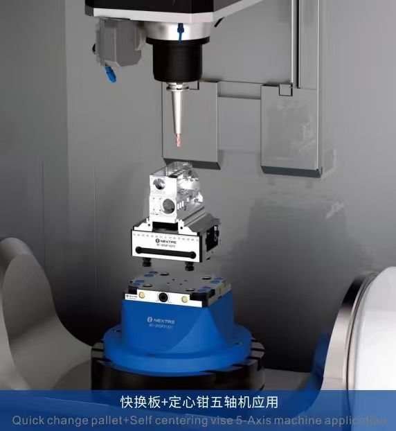
5-Axis Linkage & Complex Surface Machining
The compact design of the Nextas self-centering vise provides excellent tool accessibility for 5-axis machining. For impellers, molds, or complex structural parts, it keeps tools clear and lets you machine complex surfaces with tight tolerances.
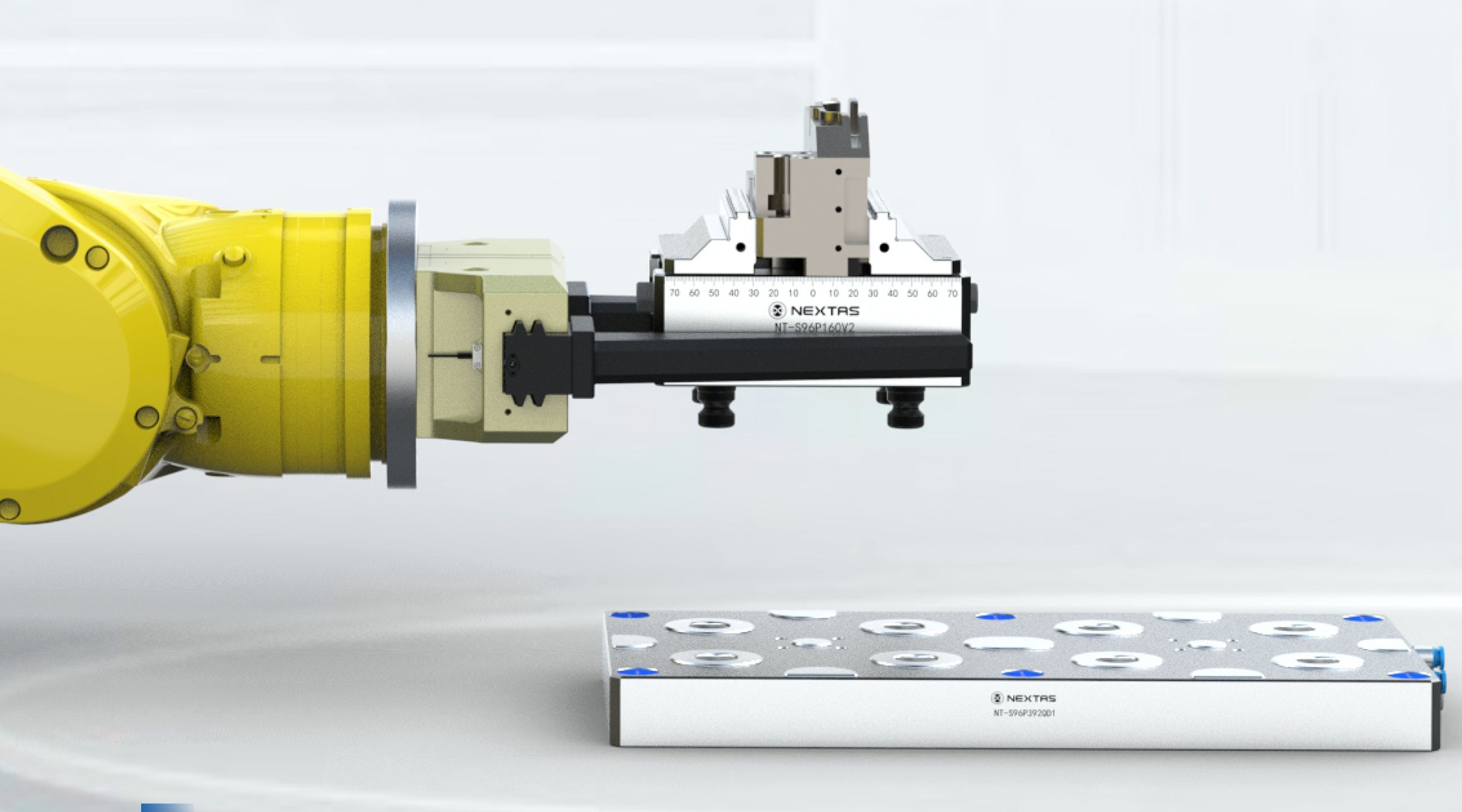
Automation Integration & Mass Production
Robotic Arm Integration
The gripping interface on the side of the vise allows for straightforward integration with robotic arms, enabling automated workpiece loading and unloading for a 24/7 unmanned production line.
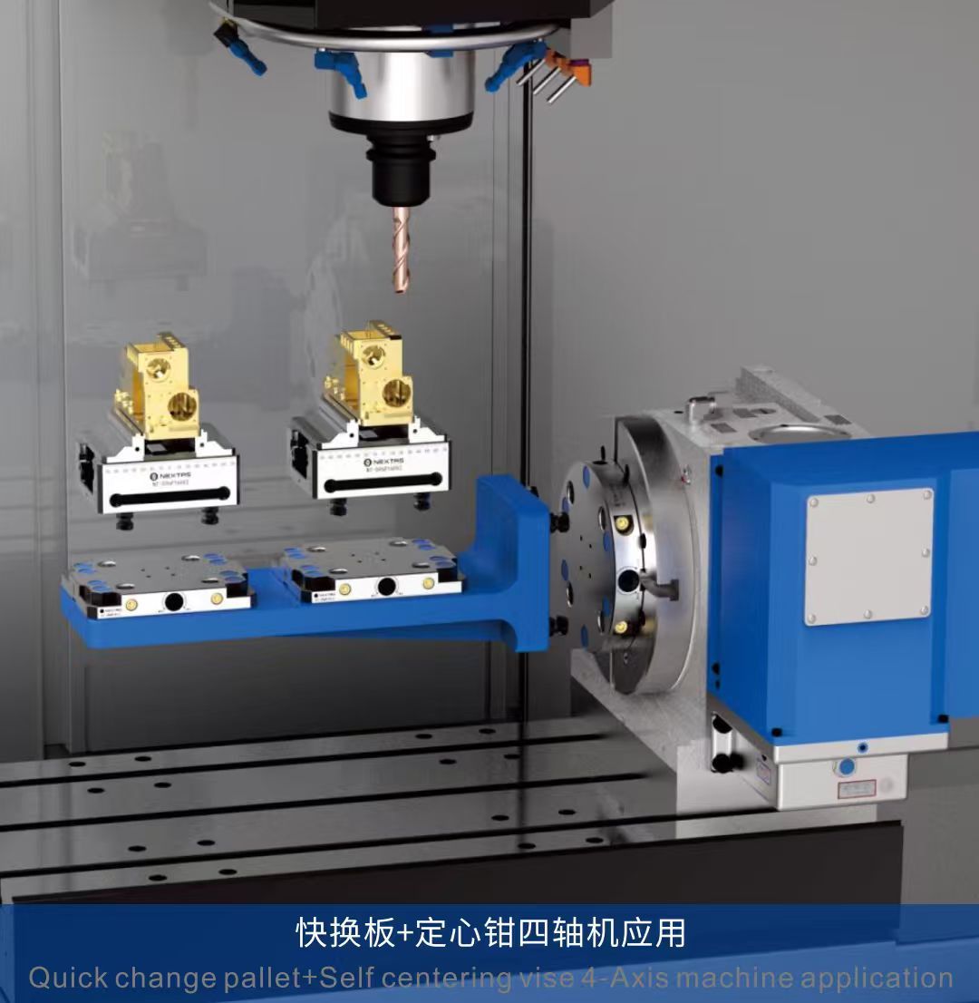
Multi-Vise Array
Arranging multiple vises on the machining center's worktable allows for the processing of multiple workpieces in a single setup, significantly boosting production efficiency.
Paired with Pallet Changer Systems
Mounting the vise on a standardized pallet allows for offline pre-setup, drastically reducing machine downtime and increasing equipment utilization.
Versatile Workpiece Clamping Capabilities
Irregular Workpieces
By using special jaws, it can securely clamp various irregularly shaped workpieces such as castings and forgings, providing a stable machining base.
4th-Axis Application
The vise's lightweight and high-rigidity features also make it suitable for mounting on a 4th-axis rotary table for multi-sided component machining.
Round Bar Workpieces
Paired with V-jaws, it can easily achieve precise and stable center clamping of round bar workpieces, suitable for machining shaft-like parts.
Real-World Case Studies
Precision and performance delivered to our clients.
Built for Production. Backed by Real Support.
Engineers care about repeatability. Procurement cares about verification. This section gives both teams what they need.
Modular Workholding & Quick-Change Jaws
Designed for a wide range of parts and setups. The modular architecture supports special jaws and a quick-change jaw design—so you can switch from castings/forgings to finished parts without wasting spindle time.
- ●Supports irregular workpieces (castings, forgings) with special jaws
- ●Fast jaw swaps for small-batch + mixed-model production
- ●Ideal with pallets / zero-point / automation cells
Engineering + After-Sales You Can Rely On
Need more than a standard vise? We support customization and provide one-to-one technical service. For complex projects, we can help with fixture solution planning, process planning, and application guidance.
- ●15+ years R&D experience (team background)
- ●Customized fixture solution based on your part geometry
- ●One-stop technical support: fixture + process + application guidance
Verified Supplier Credentials
We maintain a verified supplier presence on Made-in-China. This gives procurement teams an extra layer of confidence for supplier due diligence and compliance review.
- ●Manufacturer/Factory & Trading Company profile
- ●Certificates available on request (varies by model and product line)
- ●Platform record shows membership level / supplier rating / recent transaction history
Video Demo (Quick Overview)
A short demo helps your team confirm size, handling, and typical applications before requesting CAD files or a quote.
Setup Guide & Machining Best Practices
Faster setup, cleaner datums, and more stable cutting—especially on 5-axis.
1) Mount & Reference
For repeatability, treat the vise like a fixture: mount it once, qualify it, and reuse the same reference every changeover.
- ●Use a zero-point/pallet interface when available to eliminate re-indicating.
- ●Touch off the vise centerline once and save as a macro/work offset.
- ●For torque-heavy cuts, add an anti-rotation feature in the jaw design.
2) Jaw Choice = Part Quality
Matching jaws to material and surface condition is the easiest way to prevent slip, distortion, and chatter.
- ●Serrated jaws for castings/forgings and rough stock.
- ●Soft jaws for finished surfaces and thin-wall parts.
- ●V-jaws for round bars and shaft-like components.
3) Clamp, Verify, Run
A quick verification routine helps you protect tolerances while keeping cycle time low.
- Clean jaw faces + bed (chips are the #1 repeatability killer).
- Clamp using the recommended torque tool / module.
- Probe a reference feature (or indicate) for first-article confirmation.
- For long runs: re-check after warm-up and after jaw swaps.
Setup & Verification Checklist (for tight-tolerance CNC)
A short, repeatable routine helps a self-centering vise deliver stable results across pallets, shifts, and operators.
| Step | What to do | Tip for 5-axis / automation |
|---|---|---|
| 1. Prep | Wipe interface + jaw bed; remove burrs and chips | Treat it like a fixture: cleanliness = repeatability |
| 2. Mount | Seat on table/pallet/zero-point; apply specified tightening pattern | If you use a zero-point system, avoid re-indicating every changeover |
| 3. Qualify | Probe/indicate vise centerline once; store as a work offset/macro | Makes multi-pallet and robot loading predictable |
| 4. Clamp | Use consistent torque; confirm full jaw contact | For thin walls: use soft jaws + support pads |
| 5. Verify | Probe a reference feature (first-article) | Log the offset; watch for drift after warm-up |
| 6. Run & monitor | For long cycles: re-check after jaw swaps or tool changes | Small checks prevent big scrap batches |
Maintenance & Service Schedule
Simple care keeps the lead screw, jaw guidance, and contact surfaces performing like a precision workholding system.
| Interval | Task | Why it matters |
|---|---|---|
| Each shift | Clean chips from jaw bed and interfaces | Prevents seating errors and clamp inconsistency |
| Weekly | Inspect jaw faces; check for dings, wear, or raised burrs | Protects surface finish and reduces part movement |
| Monthly | Lightly lubricate moving contact points per your shop standard | Reduces friction and improves clamping smoothness |
| Quarterly | Verify centerline/reference with a quick indicating/probing routine | Catches gradual drift before it becomes a quality issue |
| As needed | Replace worn jaws / pads; refresh soft jaw pockets | Keeps grip reliable for high-mix production |
Typical 5-Axis Workflow
If you machine complex parts (aerospace, medical, precision molds), this workflow keeps access high and collisions low.
Roughing
Use serrated jaws + higher clamp force. Keep grip length conservative for stability.
Finishing
Switch to soft jaws or precision pads. Probe critical features to protect tolerance stack-up.
Common Use Cases
- High-mix, low-volume machining where changeover speed matters.
- 5-axis parts needing maximum tool clearance and fewer re-clamps.
- Automation cells with pallets / zero-point / robotic handling.
- Thin-wall components where controlled clamping prevents distortion.
Choose the Right Self-Centering Vise
A simple checklist for selecting model size, jaw set, and mounting interface—so you get predictable accuracy on day one.
Model guidance
Use your part envelope, cutting load, and changeover frequency to decide.
| Model | Best for | Notes |
|---|---|---|
| NT-S52P170V2 | Compact parts, 5-axis clearance, lighter rotary setups | Fast handling, lower mass, excellent for dense multi-vise layouts |
| NT-S52P210V2 | Larger parts, heavier cutting, more jaw travel | Higher clamping force and envelope for wider part families |
If you share a drawing + material + target tolerance, we can recommend jaw style and grip strategy.
What to send for a fast quote
- Part size range (min/max), material, and rough/finished surface condition
- Machine type (3-axis/5-axis) + table/pallet interface (52/96 mm etc.)
- Batch size and changeover frequency (prototype vs production)
- Any automation plan (robot loading / pneumatic or hydraulic actuation)
Related technical reading
More context for engineering teams evaluating 5-axis workholding and repeatable setups.
Self-Centering Vise: How it improves consistency
Mechanism overview, repeatability, and jaw strategy.
5-Axis + Self-Centering Vise for complex machining
Tool access, fewer re-clamps, and collision risk reduction.
Zero-Point compatibility: faster changeovers
Why standard interfaces matter for pallets and automation.
Selection • Integration • Maintenance Cheatsheet
A compact, shop-floor reference to help you choose the right configuration, integrate cleanly with your machine/automation, and keep repeatability stable in daily production.
1) Selection: pick the right configuration
| If you care most about… | Start with… | Why this helps |
|---|---|---|
| Fast changeovers / high-mix jobs | Standardize one interface (zero-point / ITS / 3R) across machines + build fixture plates/pallets. | Enables offline setup and swaps in seconds with minimal re-indicating. |
| 5-axis access and tool clearance | Choose low-profile components and plan clearance early (stack height, clamp body, wrench access). | Avoids collisions and preserves reach for deep features. |
| Lights-out / robot-tended machining | Add confirmations (clamp-OK / part-present), chip protection, and a recovery sequence. | Reduces mis-load risk and improves automation reliability. |
| Heavy roughing / high cutting forces | Increase support points and rigidity (more clamping stations, stiffer base, shorter stack-up). | Minimizes deflection and protects surface finish. |
2) Integration: what to prepare before install
| Item | Typical choice | Practical tip |
|---|---|---|
| Mounting and datums | Bolt pattern + dowel pins / keyways / reference edge | Define a master datum and keep a gauge pallet/part for quick verification. |
| Utilities | Clean, dry air with FRL; stable pressure; (hydraulic/electrical if used) | Drain FRL regularly and avoid long, restrictive hoses that slow actuation. |
| Control handshake | M-codes/PLC I/O: clamp, unclamp, clamp-OK, fault | Use timeouts + safe states; log signals to diagnose intermittent downtime. |
| Process validation | Probe macro / indicator check / first-article routine | Baseline repeatability after installation, then compare weekly. |
3) Maintenance: keep repeatability stable
| Risk / wear point | Early symptom | Prevention / quick fix |
|---|---|---|
| Chips on locating surfaces | Parts shift, repeatability drifts | Air-blow + wipe seating faces; add chip covers/air blast if needed. |
| Seals/wipers and sliding surfaces | Slow actuation, leaks, inconsistent clamp | Inspect on schedule; keep coolant/abrasives out; replace wear items proactively. |
| Loose fasteners / damaged contact faces | Unexpected misalignment, vibration marks | Torque-check; use dowels; stone minor nicks (don’t ‘machine’ the datum). |
| Contaminated air/oil | Sticky motion, alarms in automation | Improve filtration, dry air, drain bowls; keep a simple spare-kit. |
Need CAD/STEP, a mounting pattern, or a recommended setup for your part?
Contact usProduct Data & Evaluation Checklist
Buyers compare vises by accuracy, jaw range, 5-axis clearance, and how fast you can switch setups and jaws.
Key specifications
| Vise type | 5-axis self-centering vise for automation & high-mix production |
|---|---|
| Accuracy goal | Typical machining targets around 0.02 mm (setup dependent) |
| Interface standard | Supports common 52/96 mm spigot hole standards (model dependent) |
| Jaw options | Quick-change jaws; multiple jaw styles for different workpieces |
| Clamping range | Defined by jaw set; configurable for part families |
| Automation fit | Pneumatic/robot-friendly configurations available |
Tip: share your part material, machine model, and target takt time. We’ll propose the right configuration and measurable targets.
Compatibility & standards
- Designed for 5-axis accessibility: low profile and improved tool clearance.
- Pairs with zero-point quick-change systems to reduce fixture swaps.
- Supports repeat clamping with consistent center reference for symmetric parts.
Measured outcomes (before → after)
- Setup time: fewer re-indicating steps when switching part sizes within a family.
- Scrap reduction: less mis-clamp and improved centering repeatability.
- Unattended machining: stable clamp plus automation interfaces (options).
Workholding configuration
- Jaw selection: serrated/soft jaws, step jaws, or custom jaws per part geometry.
- Locator points: define datums and anti-rotation features for torque-heavy cuts.
- Workpiece plan: grip length and distortion control for thin walls.
Evidence & proof
- Jaw drawing/CAD snippet and clamping range chart for your part family.
- On-machine photos of 5-axis clearance and toolpath access.
- Inspection excerpt: repeated clamp test and parallelism/runout checks.
Delivery & support
- Application review: send part drawings for jaw recommendation and grip strategy.
- Spare jaw program: prepared jaw sets for faster SKU switching.
- Support: setup checklist and troubleshooting for repeatability issues.
Frequently Asked Questions
Your questions, answered.
How does the self-centering mechanism handle rough or asymmetrical workpieces?
Our vise is engineered with a high-precision, backlash-compensated leadscrew that applies equal force to both jaws and keeps them converging perfectly at the center, regardless of the initial workpiece shape. For rough castings or forgings, we recommend our serrated jaws, which provide solid grip, while the centering mechanism keeps the part's theoretical center always aligned with the machine's spindle.
What maintenance helps maintain repeat positioning accuracy below 0.02 mm?
To maintain peak accuracy, we recommend a simple daily cleaning routine to remove chips and coolant from the leadscrew and jaw slides. A weekly application of a light, high-pressure grease to the leadscrew (accessible via the grease nipple) is advised. The vise body is made from HRC 50-55 tool steel for durability, but the precision surfaces should be protected from impact. Regular inspection of jaw integrity is also good practice.
Can this vise be integrated with a zero-point clamping system, and how does it mount?
Yes, it's designed for straightforward integration. The vise base features standardized 52mm or 96mm (depending on the model) mounting patterns, making it fully compatible with our own zero-point systems and other common brands. This allows for changeovers in under a minute, drastically reducing setup time while locking the vise to the machine table with extreme rigidity and ±0.002mm repeatability.
You mentioned 'Automation Ready'. What specific features support this?
Automation readiness involves several key features. 1) The vise body includes standardized clamping grooves, allowing robotic grippers to load and unload the entire vise. 2) It is compatible with hydraulic or pneumatic actuation modules for fully automated clamping/unclamping. 3) Its compatibility with zero-point systems is fundamental for automated pallet changing.
Will I experience jaw lift when clamping a workpiece?
Our design specifically mitigates jaw lift. The vise mechanism includes an angular component that pulls the jaws down towards the vise bed as clamping force is applied. This 'pull-down' effect seats the workpiece flat and securely, preventing lift and vibration needed for high-precision tolerances and superior surface finishes.
Is it suitable for hobbyists or only professionals?
It works for both. Hobbyists appreciate the self-centering convenience and consistent repeatability, while professional shops benefit from high clamping force, rigidity, and reliable accuracy for CNC and 5-axis machining. If you tell us your machine and part size, we can recommend the best jaw style and vise size.
Can jaw pads be replaced if worn?
Yes. Jaw pads are designed as serviceable wear parts. You can replace them when the gripping surface is worn or when switching to a different jaw style (smooth/serrated/soft jaws). This helps maintain consistent clamping and protects your workpieces.
What causes uneven clamping, and how do I fix it?
Uneven clamping is usually caused by chips/debris on the jaw faces, a contaminated leadscrew, or using the wrong jaw type for a rough surface. Clean the jaw faces and vise bed, re-lubricate the screw according to the maintenance guide, and match the jaw style to the workpiece. If you still see issues, share a photo and we’ll help troubleshoot.
Is it compatible with CNC machines?
Yes. This vise is designed for CNC environments, including 5-axis setups. It supports repeatable positioning, rigid clamping, and common mounting options such as base mounting and integration with pallet/zero-point systems (depending on the model).
Resources & Downloads
Catalog, drawings and CAD support for project evaluation
Request the full self-centering vise catalogue, share your machine and part data for file matching, and get the right sizing guidance before setup starts.
Request Product Catalog
Get the catalogue pages covering model range, jaw options, clamping range, and typical 52 / 96 mm platform combinations.
Request 3D CAD Files (STEP)
Send your machine model, part envelope, material, and whether the vise will sit on a zero-point plate so our team can match the right STEP files faster.
Request CAD FilesRelated Products
Zero-Point Clamping Plate
Build a repeatable base under the vise so setups move from machine to machine without re-indicating.
View Details →Zero-Point Clamping System
Move vises, pallets and fixtures faster with a receiver-side changeover system built for repeatability.
View Details →Automatic Pallet Changer
Pair pallet automation with self-centering vises when unattended loading and offline setup are part of the project.
View Details →