±0.002 mm. That is two microns — roughly 1/50th the width of a human hair. In CNC workholding, this number separates shops that can ship tight-tolerance parts with confidence from those that burn hours re-indicating, re-probing, and re-running first articles. If you machine aerospace brackets, medical implants, semiconductor fixtures, or mold inserts, sub-5-micron repeatability is not optional — it is the baseline your customers expect.
But repeatability does not come from buying a premium chuck and calling it done. It is a system-level outcome: the interface geometry, surface condition, thermal state, clamping force, and verification method all contribute. Get any one of these wrong, and your "±0.002 mm" system drifts to ±0.01 mm or worse.
This guide walks through every factor that determines workholding repeatability — and gives you a practical protocol to verify it on your own shop floor.
Key takeaways (fast scan)
- Datum interface condition is the #1 factor — clean, hardened, and undamaged surfaces are non-negotiable.
- Thermal discipline matters: 1 °C on a 300 mm steel fixture = ~3.5 µm shift.
- Clamping force must be sufficient to resist cutting loads but controlled to avoid part distortion.
- Zero-point systems with taper-type positioning deliver inherent self-centering for repeatable datum return.
- Verify, don't assume: run a 20-cycle seat/unseat test with a DTI or touch probe before production.
1) Why ±0.002 mm repeatability matters
Repeatability in workholding means: can you remove a pallet or fixture from the machine, and re-seat it to the same datum position within a defined tolerance band? For ±0.002 mm class, the total range across many seat/unseat cycles must stay within 0.004 mm (4 µm).
What it enables
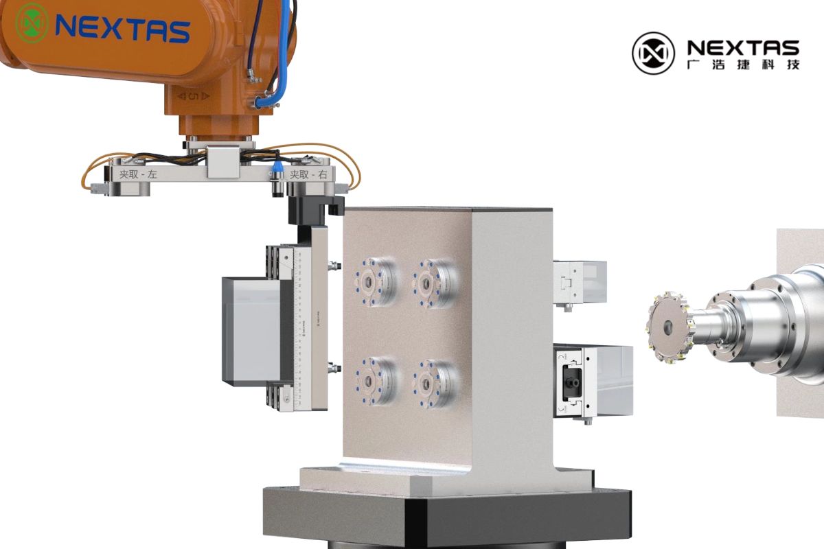
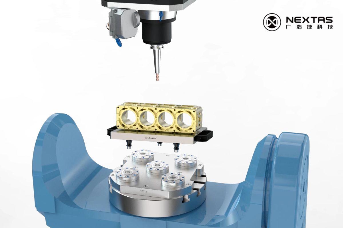
- Offline setup: Build fixtures at a prep station while the spindle keeps cutting. Zero-point pallets swap in seconds, not minutes.
- Multi-operation consistency: Move a workpiece from CNC to CMM to EDM to wire-cut and back — without losing your zero reference.
- Reduced first-article time: When the fixture always returns to the same spot, probe verification replaces manual indicating.
- Automation readiness: Robotic pallet changers and FMS cells depend on deterministic datum return. If repeatability drifts, the cell stops.
The cost of poor repeatability
Every extra minute spent indicating a fixture costs spindle time. If your shop runs 3 shifts and each changeover adds 10 minutes of re-indicating, that is 30 minutes per day — over 180 hours per year of lost production per machine. At a typical shop rate, that translates directly to tens of thousands of dollars in lost margin.
2) Datum interface design: the foundation
The datum interface is where the fixture meets the machine table (or sub-plate, or pallet). Every micron of error at this interface propagates directly to the workpiece. Two design principles matter most:
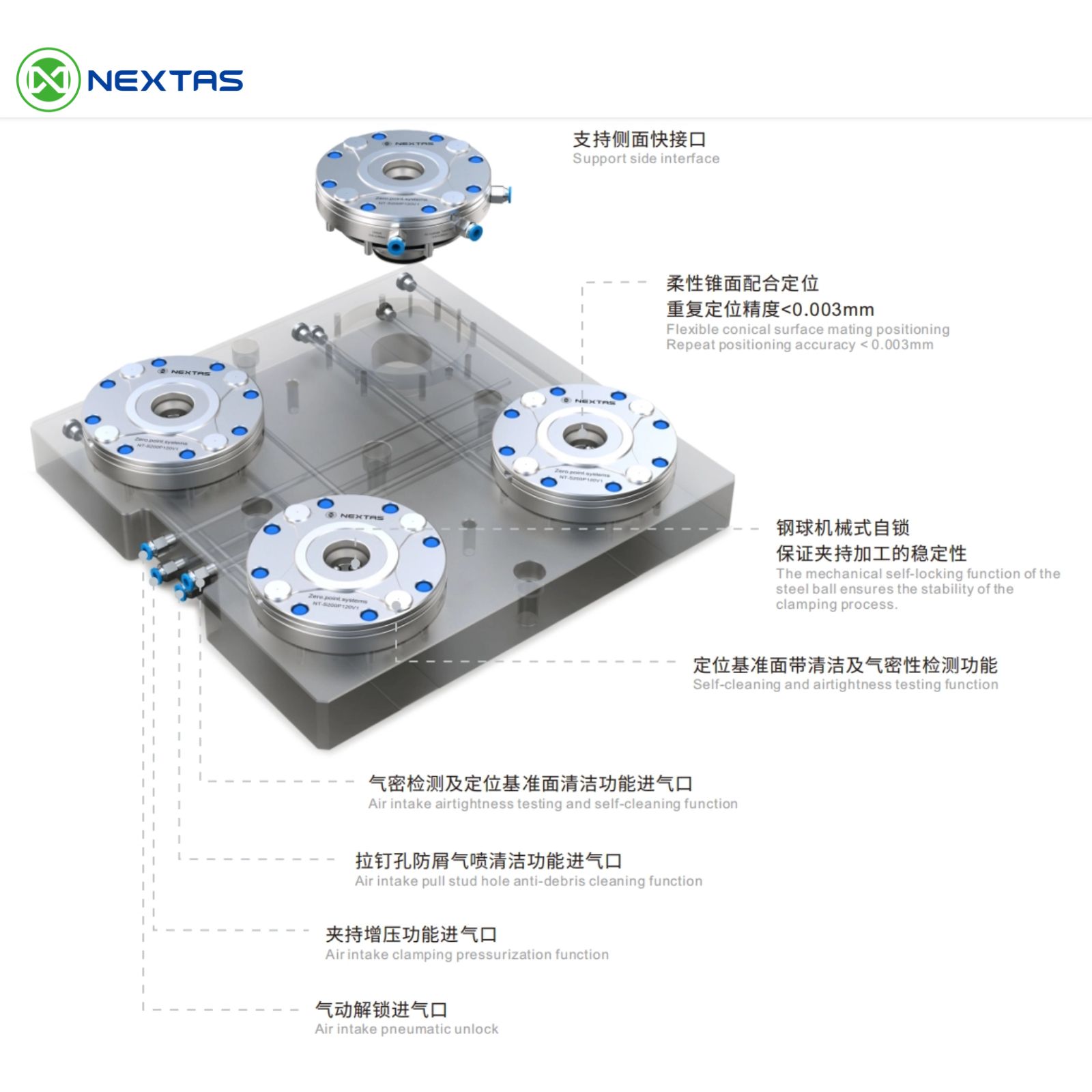
Taper-type self-centering geometry
Flat-on-flat datum interfaces rely on friction and edge contact. Over thousands of cycles, micro-wear and chip contamination cause "float" — the fixture shifts slightly each time it is re-seated. Taper-type positioning (as used in Nextas zero-point chucks) solves this by guiding the pull stud into a conical seat that self-centers as clamping force is applied. The taper eliminates micro-gaps and provides a natural, repeatable locating mechanism.
Material hardness and wear resistance
The datum surfaces must be harder than any chip or debris that might land on them. Nextas zero-point chucks use hardened stainless steel (typically 58–62 HRC) for the clamping interface. This prevents micro-indentation from swarf and maintains geometric accuracy across tens of thousands of clamping cycles.
Design rule of thumb: If your datum interface material is softer than the workpiece material's chips, repeatability will degrade over time. Hardened stainless steel or hardened tool steel interfaces are the minimum for sub-5-µm repeatability targets.
3) Surface preparation & cleaning discipline
The most precisely machined datum interface becomes useless if a 10 µm chip sits between the mating surfaces. Surface preparation is where many shops lose repeatability without realizing it.
Pre-seat cleaning protocol
- Air blast: Use clean, dry, filtered shop air (minimum 0.5 MPa) to blow out the chuck cavity and pull stud socket before every seat. Moisture in the air line deposits residue — use a coalescing filter.
- Wipe-down: For critical work, follow the air blast with a lint-free wipe dampened with a fast-evaporating solvent (isopropyl alcohol or dedicated fixture cleaner).
- Inspect visually: A quick visual check of the pull stud taper and the chuck bore takes 5 seconds and catches chips that air alone missed.
Chip protection by design
Prevention beats cleaning. Nextas zero-point chucks incorporate sealed chuck bores with integrated air purge. A small positive air pressure keeps the internal mechanism free of coolant and swarf during machining. When the chuck is empty (stud removed), the bore stays protected — so the next clamping cycle starts clean.
4) Thermal management for sub-5-micron accuracy
Steel expands at roughly 11.7 µm/m/°C. For a 300 mm fixture plate, a 1 °C temperature change produces approximately 3.5 µm of dimensional shift — already a significant fraction of your ±0.002 mm budget. Thermal management is not optional at this tolerance level.
Practical thermal rules
- Stabilize before measuring: After a heavy roughing cut, the fixture and workpiece are warm. Allow 15–30 minutes of stabilization (or run a finishing pass with coolant) before taking critical measurements.
- Consistent coolant temperature: If your coolant temperature swings ±3 °C through the day, your fixture dimensions swing with it. A chiller or temperature-controlled coolant system pays for itself in reduced scrap.
- Machine warm-up routine: Run the spindle and axes through a warm-up cycle before first-article verification. Most CNC machines need 20–40 minutes to reach thermal equilibrium.
- Symmetric fixture design: A symmetric fixture plate expands uniformly. An asymmetric design creates differential thermal growth that shifts the datum unpredictably.
| Material | CTE (µm/m/°C) | Expansion per 1 °C (300 mm part) | Impact on ±0.002 mm budget |
|---|---|---|---|
| Steel (carbon/alloy) | 11.7 | 3.5 µm | Consumes 88% of budget |
| Stainless steel | 17.3 | 5.2 µm | Exceeds budget |
| Aluminum (6061) | 23.6 | 7.1 µm | Far exceeds budget |
| Invar 36 | 1.2 | 0.36 µm | Negligible |
Practical tip: If your shop temperature varies more than ±2 °C through the day, thermal effects will dominate your repeatability error. Investing in climate control for the machine area is often cheaper than chasing tolerance with better tooling.
5) Clamping force strategy: enough but not too much
Clamping force must accomplish two things: hold the workpiece securely against cutting loads, and seat the datum interface fully. But excessive clamping force introduces its own problems — elastic deformation of the fixture or workpiece that shifts the datum when released.
Mechanical self-locking for consistent force
Pneumatic or hydraulic clamping can vary with supply pressure. Mechanical self-locking (spring + steel ball) as used in Nextas zero-point systems provides a fixed, repeatable clamping force regardless of air supply fluctuations. The pneumatic circuit only opens the chuck; the spring pack does the clamping. This means clamping force is the same on the first cycle and the ten-thousandth cycle.
Deformation budget
For thin-walled workpieces or light fixture plates, calculate the elastic deformation under clamping force using basic beam theory or FEA. If the deformation exceeds your repeatability target, you need either more support points or a lower-force clamping strategy (e.g., vacuum assist, conformal jaws, or distributed clamping).
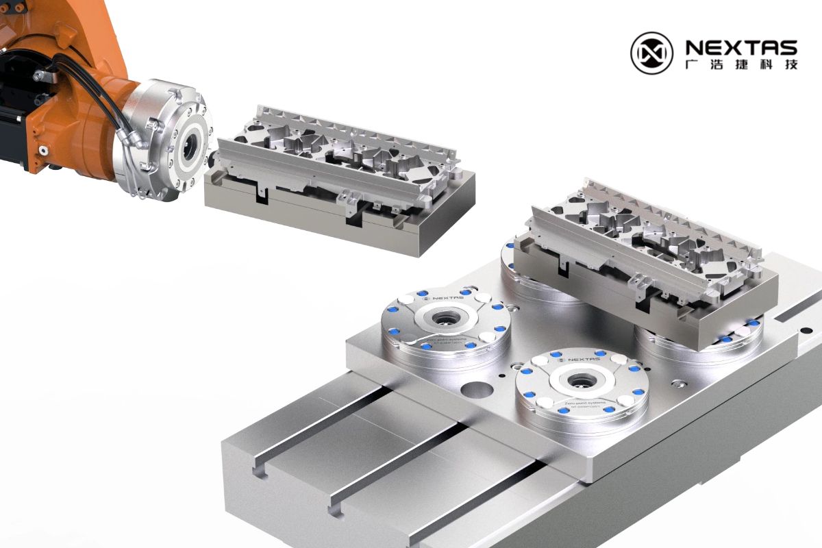
6) Zero-point clamping systems for ±0.002 mm
A well-designed zero-point clamping system integrates all of the above principles into a single, standardized interface. Here is how the Nextas product range maps to repeatability targets:
| System | Repeatability | Clamping Force | Key Feature | Best Application |
|---|---|---|---|---|
| P85 | <0.003 mm | 4,000 N | Compact, 5-axis friendly | Small electrodes, precision parts |
| P120 | <0.003 mm | 12,000 N | Standard milling workhorse | General CNC, fixture pallets |
| P195 | <0.003 mm | 40,000 N | Heavy-duty pull-down | Large workpieces, aggressive roughing |
| BDS Series | <3 µm | 60,000 N | Ultra-precision positioning | Tight-tolerance cells, inspection fixtures |
All Nextas zero-point chucks share these repeatability-enabling features:
- Taper-type self-centering for consistent datum return
- Hardened stainless steel interfaces (58–62 HRC) for long-term geometric stability
- Mechanical self-locking for pressure-independent clamping force
- Integrated air purge for chip and coolant protection
- Seat-check (airtightness verification) for automation confidence
7) Shop-floor verification protocol
Claims on a datasheet do not replace verification on your machine, with your fixture, under your shop conditions. Here is a step-by-step protocol to confirm ±0.002 mm repeatability:
Equipment needed
- Dial test indicator (DTI) with 1 µm resolution, or machine-mounted touch probe
- Calibrated test bar or ring gauge mounted on the fixture
- Data recording sheet (or digital logger)
Procedure
- Install the zero-point base plate on the machine table. Verify it is flat and torqued to spec.
- Mount the test fixture (with test bar) onto the zero-point system. Clamp fully.
- Set the DTI to zero on two orthogonal points (X and Y) on the test bar.
- Record the initial reading.
- Unclamp, lift the fixture completely clear of the zero-point receivers, and re-seat. Clamp again.
- Record the new DTI readings in X and Y.
- Repeat steps 5–6 at least 20 times. More cycles give higher statistical confidence.
- Calculate: Range = Max reading − Min reading. For ±0.002 mm class, the range must be ≤0.004 mm in both X and Y.
Pro tip: Run the test at the start of a shift (cold machine) and again 2 hours into production (warm machine). If the warm-state results differ significantly from cold-state results, thermal effects are dominating your repeatability budget.
8) Common repeatability killers & fixes
| Problem | Symptom | Root Cause | Fix |
|---|---|---|---|
| Chips on datum surface | Random repeatability scatter | Inadequate cleaning between seats | Air purge + wipe protocol; install chip shields |
| Thermal drift | Readings shift consistently in one direction through the day | Shop or coolant temperature changing | Climate control; coolant chiller; stabilization time before measurement |
| Worn pull stud taper | Repeatability degrades over months | Soft material or excessive cycle count without inspection | Replace pull studs on schedule; use hardened studs; inspect taper with gauge |
| Inconsistent clamping force | Repeatability varies with air pressure | Relying on pneumatic force for clamping (no mechanical lock) | Use mechanical self-locking systems; regulate and monitor air supply |
| Over-positioning (binding) | Fixture hard to seat; inconsistent landing | Too many locating studs constraining the same DOF | Use 1 locating + 1 compensating + N clamping stud layout |
| Base plate not flat | Repeatability good in X, poor in Z | Sub-plate or machine table has surface error | Resurface or regrind the base plate; verify with straight edge + feeler gauge |
Need a repeatability audit for your setup? Send us your machine model, fixture layout, and tolerance target — we will review your datum strategy and recommend improvements.