Understanding the mechanics of backlash and internal play
Self-centering vises rely on a synchronized lead screw and internal nut assembly to clamp workpieces with repeatable accuracy. When you turn the handle, the lead screw rotates inside the nut, driving the jaw carriage forward. The beauty of this design lies in its simplicity: both jaws move inward simultaneously, centering the part automatically without operator adjustment.
But backlash—the looseness between the lead screw and the internal nut—is the silent killer of precision. Even small amounts of play (0.1 mm to 0.3 mm over time) translate into jaw lag, where one jaw moves before the other, or centering drift, where the part is never held at the true geometric center. This drift compounds with each clamp cycle and accelerates wear on the ball bearing races and thrust surfaces.
The most dangerous type of backlash is axial play in the thrust bearing pack. If the bearing washers or the nut boss wear down, the lead screw can shift forward and backward slightly during clamping, creating micro-movements that throw off part centering by 0.05 mm to 0.15 mm per cycle. Over 50,000 clamping cycles in a production month, that is equivalent to scrap or rework on dozens of parts.
Advanced backlash mitigation strategies
There are three approaches to controlling backlash in a production self-centering vise. Each has trade-offs in complexity, cost, and operational impact.
Strategy 1: Preload Adjustment via Collar and Locking Nut
A locking collar sits on top of the lead screw, outside the main nut assembly. By torquing it to a calibrated force (typically 12 to 18 N·m, depending on vise size), you can compress the nut seat slightly, creating a small amount of controlled friction that eliminates free play. This is the most common approach in field maintenance because it requires only a wrench and a torque spec, and it can be checked and adjusted without disassembling the vise.
Strategy 2: Nut Replacement with a Ground Precision Nut
Over time, the internal nut thread pitch wears unevenly, especially if the vise has been clamping abrasively at high load cycles. The only permanent fix is to replace the nut with a new precision-ground part. Ground nuts have tighter tolerances (IT5 or IT6 vs. IT7 standard), reducing thread engagement looseness to under 0.03 mm. This approach is more expensive but guarantees backlash control for another 200,000+ clamping cycles.
Strategy 3: Lead Screw and Nut Bundle Replacement
If the lead screw itself is bent, stripped, or heavily worn, or if the nut is beyond salvaging, both parts must be replaced as a matched pair. This is the most invasive approach but yields the tightest backlash control and the longest service life. A new lead screw and nut pair can be preloaded to achieve axial play under 0.02 mm.
| Strategy | Mechanical Mechanism | Primary Benefit | Operational Drawback |
|---|---|---|---|
| Preload collar adjustment | Locking collar compresses nut seat via friction | Can be done in-place; no disassembly needed | Temporary fix lasting 6-12 months in high-volume production |
| Precision nut replacement | Ground internal nut reduces thread pitch wear | Extends service life to 200,000+ cycles | Requires disassembly and part sourcing; downtime ~2 hours |
| Lead screw + nut bundle replacement | Complete drivetrain replaced with new matched pair | Backlash guaranteed under 0.02 mm; longest lifespan | Most invasive; full vise disassembly; downtime ~3-4 hours |
| Intelligent preload via spring tension | Preloaded wave spring applies consistent axial force | Backlash self-compensates as nut wears; no manual tweaking | Requires original design; cannot retrofit to older vises |
Thrust bearing teardown and re-calibration
The thrust bearing pack is where the lead screw meets the jaw carriage. It must absorb all the clamping force along the screw axis while allowing smooth rotation. This pack typically consists of two hardened thrust washers, a precision ball bearing or needle bearing, and a preload collar that holds everything in place.
Over time, contamination from grinding dust, coolant residue, and metal fines works its way into the bearing races, creating micro-pitting and uneven preload loss. When you notice the handle feeling rough, requiring more effort to clamp, or the vise centering drifting slightly during a clamp cycle, the bearing pack is usually the culprit.
Here is the step-by-step process for a proper thrust bearing inspection and re-calibration:
- Step 1: Remove the handle and fully unscrew the lead screw from the jaw carriage. You should encounter resistance near the bottom of the stroke due to preload.
- Step 2: Use a soft brush and compressed air to remove all surface debris from the thrust bearing surfaces. Do not spray cleaners directly into the bearing; instead, use IPA or a light penetrating oil on a cloth.
- Step 3: Inspect the hardened thrust washers for discoloration, pitting, or spalling. Any visible wear pattern indicates bearing failure and requires replacement.
- Step 4: Loosen the preload collar slowly, noting the torque required to rotate the lead screw at each turn. A sudden drop in required torque indicates bearing damage or nut slippage.
- Step 5: Remove the bearing and thrust washers, clean them thoroughly, and measure them for dimensional loss. The thrust washers should measure within 0.05 mm of their design thickness.
- Step 6: Reassemble with new bearing or thrust washers if wear is detected. Preload the collar to a torque of 12 to 18 N·m, checking that the handle rotates smoothly and evenly from fully open to fully closed.
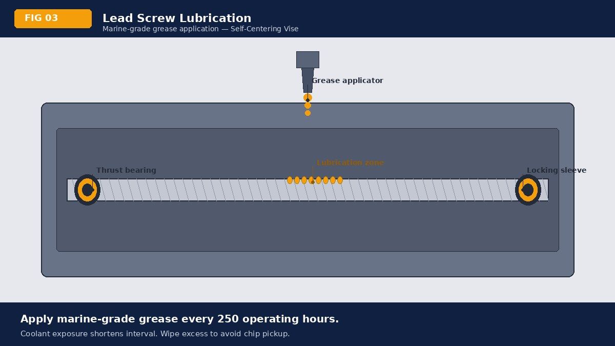
- Step 7: Install a small amount (2-3 grams) of marine-grade grease on the bearing races after reassembly. This protects the bearing from coolant intrusion during the next production run.
The Collar Synchronization Secret: Many technicians apply torque to the collar using a standard wrench and an estimate. But the correct approach is to use a torque wrench set to your vise model's specification. If you do not have the specification, the rule of thumb is: tighten the collar until the handle requires 3 to 5 newtons of force to rotate through the middle of the clamp stroke, then lock it with the set screw. This "feel test" is more reliable than a single static torque measurement.
Metrological precision: centerline calibration protocols
Even a vise with zero backlash will not center a part correctly if the jaw alignment or the internal cam profile has drifted. Centerline drift is a form of systematic error that emerges over thousands of clamping cycles, especially in high-speed machining or when clamping irregular workpiece geometries.
To verify centerline accuracy, you need a precision dial indicator and a test bar. Mount the vise on your machine table and secure a 25 mm diameter precision cylindrical test bar in the vise jaws, clamping to a moderate force (about 50% of rated clamping force). Using a dial indicator mounted in your spindle, measure the total indicated runout (TIR) of the test bar across its length. The acceptable range for a high-precision vise is under 0.03 mm (30 microns) TIR.
If TIR exceeds 0.05 mm, the most common causes are:
- Jaw wear or chipping: The clamping surfaces have worn unevenly or developed small chips that prevent full jaw closure.
- Internal cam profile erosion: The tapered cam surface inside the vise body has lost its tight profile tolerance, reducing the synchronization force between the two jaws.
- Nut-to-jaw carriage alignment loss: The internal carriage bracket has shifted or bent, causing the nut to drive one jaw slightly forward of the other.
The solution depends on severity. For TIR between 0.03 and 0.05 mm, a thorough cleaning and re-tightening of all internal fasteners (jaw set screws, carriage bracket fasteners) often restores accuracy. For TIR above 0.05 mm, jaw replacement or body re-machining is required, and it is time to consult your vise manufacturer or a precision workholding specialist.
Intelligent lubrication and coolant management
Lubrication is not a one-time application; it is a continuous strategy that must evolve with your production environment. The lead screw and internal nut are designed for light-to-medium oil films, not heavy grease. Yet most machinists over-lubricate with general-purpose lithium grease, which hardens under coolant and accelerates wear.
Type 1: Water-Soluble Coolant Environments
If your vise is exposed to CNC coolant spray, standard oil or light grease is washed away in minutes. The best choice is a heavy-duty marine-grade grease with a water-resistant binder (such as lithium complex or PAO synthetic) combined with an anti-corrosion additive package. Apply 1 to 2 grams every 2,000 clamping cycles (typically monthly in a moderate production shop), focusing on the lead screw threads and the thrust bearing outer races.
Type 2: Dry or Semi-Dry Machining
If your vise rarely sees coolant (e.g., boring, drilling, or tapping operations), you can use a lighter spindle-grade oil or a non-melting synthetic grease. The advantage is that the lubricant stays in place, providing continuous film strength without hardening. Apply 1 gram every 5,000 to 10,000 cycles or quarterly, whichever comes first.
Type 3: High-Temperature or Aerospace Production
For critical work (aerospace, medical device machining, or die-casting), consider a molybdenum disulfide or copper-based anti-seize compound instead of traditional grease. These compounds create a boundary layer that survives extreme clamping loads and coolant exposure. They are messier to apply but provide the longest service life between maintenance intervals (6 to 12 months).
A practical lubrication schedule that works across most production shops:
- Daily: Wipe the external vise body with a lint-free cloth to remove chips and coolant residue.
- Weekly: Inspect the handle for unusual grinding or stiffness during operation.
- Monthly: Apply 1 to 2 grams of marine-grade grease to the visible parts of the lead screw (if accessible without disassembly).
- Quarterly: Perform a full backlash check and a TIR measurement on a precision test bar.
- Semi-annually: Consult your vise manufacturer's recommended maintenance document and perform any preventive component checks or preload adjustments they suggest.
Operational integrity: eliminating the human factor
The most dangerous threat to vise lifespan is operator over-torquing. Many shops issue generic vises without clear clamping force guidelines, and operators instinctively over-tighten to "be safe." Some go further and use a cheater bar on the handle to ramp up clamping force beyond the vise's design limits.
The Dangers of Over-Torquing: When you exceed the rated clamping force (typically 8,000 to 12,000 N for a 96 mm vise), the internal lead screw begins to yield at the thread root. After 5 to 10 over-torquing incidents, micro-cracks develop and propagate along the screw axis, causing permanent deformation. The nut threads are thread-locked to the lead screw threads but cannot deform as much; instead, they slip relative to the screw, creating instant backlash and jaw lag that no amount of preload adjustment can fix.
Balancing Clamping Loads: The best practice is to clamp with the minimum force required to hold the part securely throughout the machining cycle. For a typical 25 mm diameter round bar in a 96 mm self-centering vise, a clamping force of 6,000 N (about 60 N hand force at the end of a 100 mm handle) is sufficient for turning, milling, and drilling operations. Teach your operators to use a light touch and trust the vise's centering action rather than muscling the handle.
Jaw and Nut Synchronization Secret: A worn or damaged vise will sometimes clamp off-center, tempting the operator to re-position the part by hand or by over-torquing. Instead, train operators to release the vise immediately if they sense centering lag, and then inspect the vise before the next job. A 5-minute vise inspection can prevent a 2-hour downtime caused by part scrap or rework.
Comprehensive CNC vise maintenance schedule
| Maintenance Interval | Task | Inspection Criteria | Action if Issue Found |
|---|---|---|---|
| Daily | External cleaning and visual check | Look for chips, coolant pooling, or visible cracks in vise body or jaws | Wipe dry and remove chips; do not use vise if cracks are visible |
| Weekly | Handle feel test and centering lag assessment | Does the handle feel smooth through the entire clamping stroke? Does the part hold dead center? | If grinding or lag is noted, schedule a full inspection for the next maintenance window |
| Monthly | Lubrication refresh and fastener check | Apply 1-2 grams marine-grade grease; verify jaw set screws are tight (1.5 N·m) | Re-tighten any loose fasteners; replace grease if old grease is discolored or hardened |
| Quarterly | Backlash check and TIR measurement | Backlash under 0.03 mm; TIR of precision test bar under 0.03 mm | If backlash exceeds 0.05 mm, perform preload adjustment or schedule nut replacement; if TIR exceeds 0.05 mm, schedule jaw inspection |
| Annually | Full thrust bearing inspection and calibration | Bearing races smooth (no pitting); thrust washers within 0.05 mm of design thickness; preload collar torque 12-18 N·m | Replace bearing or thrust washers if wear detected; re-torque preload collar to spec |
Conclusion: the integrated approach to precision
A self-centering vise is a precision machine tool, not a hammer. Its repeatability and accuracy depend on an integrated system of backlash control, bearing preload, lubrication, and operator discipline. No single maintenance task will extend your vise lifespan by 300,000 cycles; instead, it is the combination of regular backlash checks, quarterly bearing inspections, intelligent lubrication, and a workplace culture that rejects over-torquing that compounds to real, measurable improvements in part quality and vise durability.
Start with a baseline TIR check and backlash measurement. Then follow the quarterly inspection schedule and the monthly lubrication protocol. Within six months, you will notice smoother handle action, tighter part centering, and fewer scrap parts due to vise-induced runout. Your bottom line improves, and your operators gain the confidence that comes from using well-maintained, reliable equipment.
Upgrade Your CNC Workflow
Ready for micron-level repeatability?
At Nextas Tech, we specialize in ultra-precision workholding solutions including Self-Centering Vises, Zero-Point Clamping Systems, and Pneumatic Automation fixtures. Contact our engineering team with your machine model and part drawings.